Chapter 6 Hardware Installation
55
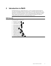
Step 5 Set Jumpers,
Continued
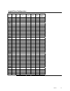
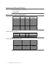
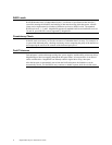
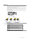
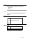
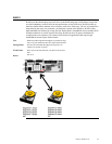
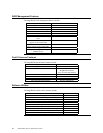
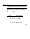
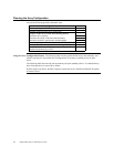
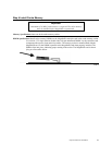
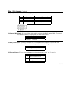
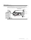
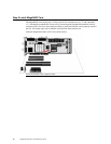
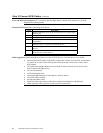
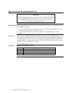
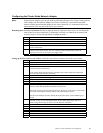
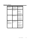
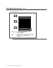
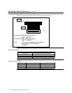
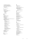
J14 Serial Port
J14 attaches to a serial cable. The pinout is:
Pin Signal Description Pin Signal Description
1 Carrier Detect 2 Data Set Ready
3 Receive Data 4 Request to Send
5 Transmit Data 6 Clear to Send
7 Data Terminal Ready 8 Ring Indicator
9 Ground 10 CUT
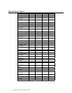
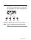
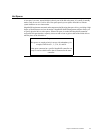
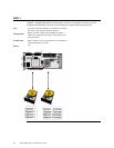
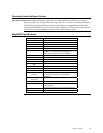
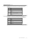
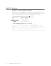
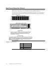
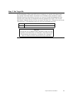
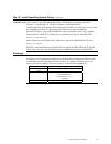
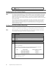
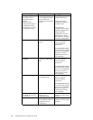
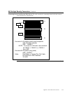
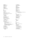
J19 Onboard BIOS Enable
J19 is a 2-pin berg which enables or disables MegaRAID onboard BIOS. The onboard
BIOS should be enabled (J19 unjumpered) for normal board position.
J19 Setting Onboard BIOS Status
Unjumpered Enabled
Jumpered Disabled
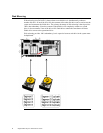
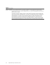
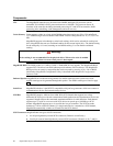
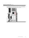
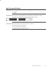
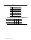
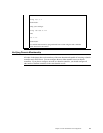
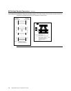
J17 Dirty Cache LED
J17 is a two-pin connector for an LED mounted on the computer enclosure. The LED
indicates when the data in the cache has yet to be written to the storage devices.
Pin Description
1High
2 Dirty Cache Signal
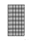
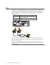
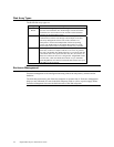
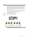
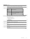
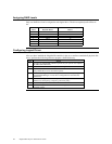
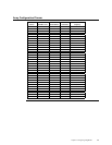
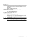
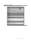
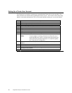
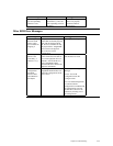
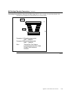
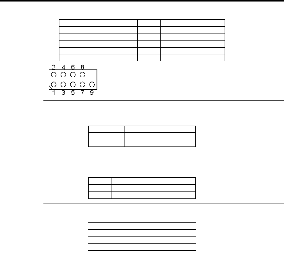
J23 External Battery
J23 is a 5-pin berg that attaches to the optional battery pack. The J23 pinout is:
Pin Signal Description
1 +BATT Terminal (red wire)
2 Thermistor (white wire)
3 -BATT Terminal (black wire)
4 BATDQ (no wire)
5 Ground (no wire)
Cont'd