CN8600 User Manual
10
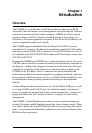
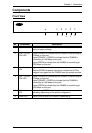
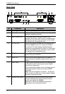
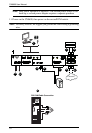
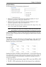
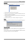
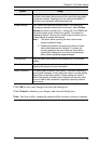
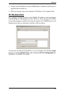
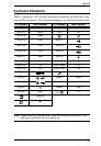
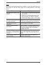
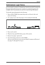
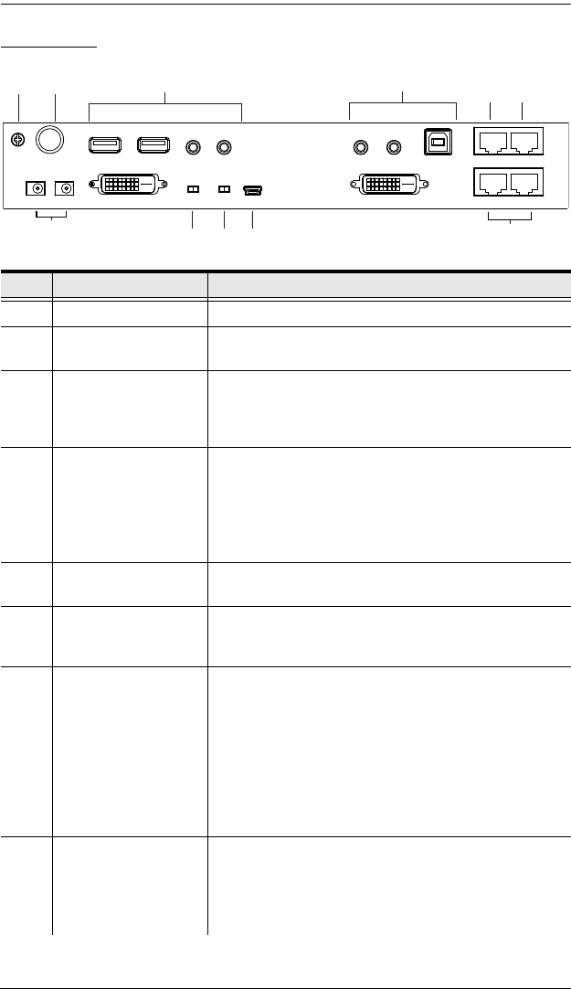
Rear View
No. Component Description
1 Grounding Terminal The wire used to ground the unit connects here.
2 Control Port This port only connects to an optional control box that
requires a separate purchase.
3 Local Console Port Connect the cable for the local console (USB
keyboard, DVI monitor, USB mouse, microphone and
speakers) to this port. Each connector is color coded
and marked with an appropriate icon.
4 PC/KVM Port Use the KVM cable provided with this package that
links the CN8600 to your PC / Server for this port.
Connect the DVI video display, keyboard/mouse,
microphone and speakers to the server or KVM switch
that you are installing. Each connector is color coded
and marked with an appropriate icon.
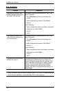
5 PON Port Use a RJ45-to-Serial adapter (SA0142) cable to
connect this port to PN0108.
6 Serial Port Use a RJ45-to-Serial adapter (SA0142) cable to
connect this port to another network device, such as a
modem.
7 Power Jacks Plug the power adapter provided with this package into
an AC power source, then plug the power adapter
cable into any power jack.
Plug another power adapter into an AC power source,
then plug the power cable into the other CN8600
power jack.
Note: Dual power operation is optional – the second
power source is for back-up; a second power adapter
requires a separate purchase.
8 Console Lock Switch Use this switch to lock the console so that remote
access is disabled (view only) and only the local
console can operate the CN8600.
When set to unlock, the CN8600 grants access
depending on the configuration stored.