


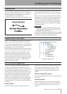
18 TASCAM HD-P2 Owner's Manual
HD-P2 Screens and Menus
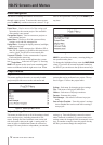
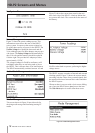
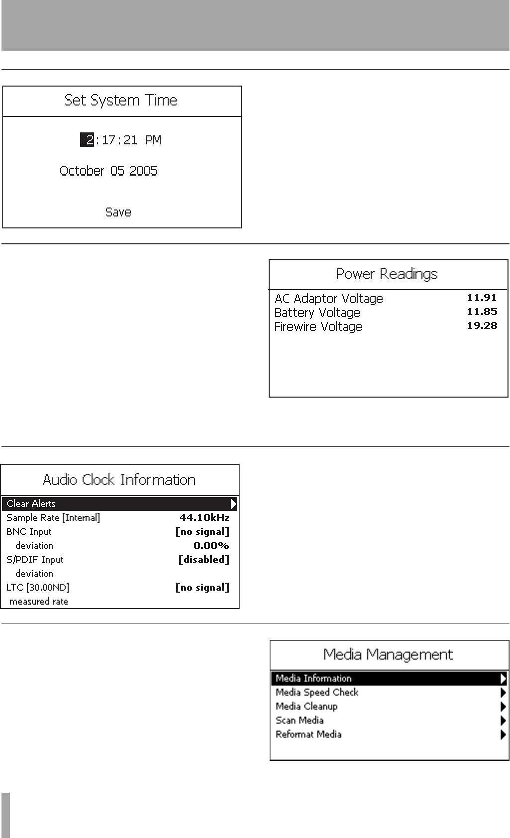
Set System Time
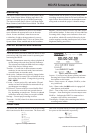
Figure 21 shows the current time stored in the real-
time clock chip of the HD-P2. A backup lithium bat-
tery powers this clock. The screen shows the status of
this battery.
Figure 21 - Set System Time Screen
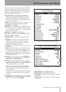
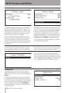
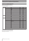
Audio Clock Management
The HD-P2 supports a number of internal and external
clocking options. Figure 23 shows the current sample
rate along with the values of any external signals, and
the measured deviance between their values and what
the HD-P2 expects.
Whenever there is an error with a clock source falling
out of spec the HD-P2 shows
[error]
next to the item.
The
Clear Alerts
option is used to clear these errors.
Figure 23 - Audio Clock Information Screen
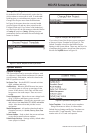
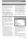
Media Management
This screen shown in Figure 24 provides tools for
checking media useage and formatting/erasing CF
media.
Figure 24 - Media Management Screen
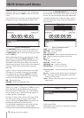
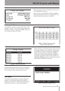
Power Management
Figure 22 - Power Reading Screen
Figure 22 shows the power readings screen. This
information screen shows the state of the HD-P2
power system. It reports on the current voltage lev-
els of the three sources of power for the HD-P2. The
FireWire Voltage
level should be between 8 and 40
Volts, although some FireWire adaptors may not pro-
vide power. The
Battery Voltage
should nominally be
above 10 volts and the batteries should be replaced
if below eight. The provided AC adaptor provides
approximately 12 VDC.
The voltage readings for FireWire and battery will
read higher when they are not being used to power
the HD-P2. This is because there is no load on them.
The HD-P2 automatically switches between AC and
FireWire when both are present, preferring the higher
voltage source.