


31
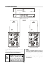
Mains switch
(TCI 1 RE and TCI 2 E only)
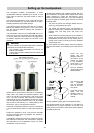
The foil membrane of electrostatic drive units needs to
be charged up using a high voltage, and that is why the
TCI 1 RE and TCI 2 E feature a mains input socket and a
mains switch.
The mains switch operates as a mains isolation
switch, i.e. when switched off all the electrical sub-
assemblies in the speaker are permanently disconnected
from the mains power supply.
The electrostatic treble units are equipped with an auto-
matic power-on circuit which responds to the input sig-
nal. The high voltage for the electrostatic driver switches
itself on automatically when a music signal is present at
the speaker input. If the input signal at the TCI 2 E is
absent for longer than about 5 minutes, the high voltage
is automatically switched off again; in the case of the
TCI 1 RE the complete valve output stage switches itself
off after about 30 minutes without an input signal. Howe-
ver, in both cases a few sub-assemblies remain con-
nected to mains voltage.
A monitor LED below the electrostatic unit on the front of
the cabinet glows to indicate that the unit is switched on.
Notes:
We recommend that you should run-in the electrostatic
drivers for about 5 minutes before listening to music, to
give time for the repeaters to charge up the foil membra-
nes.
It is also possible to switch on the TCI 1 RE’s electrosta-
tic driver and valve output stage permanently using a
control voltage (see following section).
Caution: on no account remove the
protective earth!
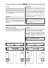
Additional controls on the TCI 1 RE
Signal input (Cinch) with level adjustor
The pre-amplifier output signal can be fed
directly to the valve output stage of the e-
lectrostatic treble unit via this socket.
The LINE LEVEL trimmer can then be used
to adjust the sensitivity of the Cinch input to
match the amplification factor of the power
amplifiers which are used for the mid-range
and bass ranges.
For power amplifiers the centre (detent) position
should be set (amplification factor = 37, corresponding
to 31.5 dB).
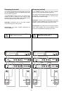
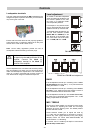
Automatic power-on circuit for valve output stage
The electrostatic treble unit’s valve output
stage is fitted with an automatic power-on
circuit which responds either to the input signal
or to a control voltage; it can also be set to
continuous operation.
ON
AUTO
The valve output stage switches on automati-
cally if a music signal is present at the speaker
input. If the input signal is absent for longer
than about 30 minutes, then the valve output
stage switches off automatically.
Note:
If the output stage is switched on automatical-
ly, it takes about 1 minute for the valves to
warm up, and about 5 minutes for the e-
lectrostatic foil to be charged up using the
repeater; only after this period does the treble
response become capable of delivering full
volume..
ON
CTRL
The valve output stage remains switched on as
long as a control voltage is present at the
control voltage input CTRL. This position is
designed for use with pre-amplifiers which
feature a suitable control output; this feature is
available as an option for pre-amplifiers.
ON
CONT
At this setting the valve output stage remains
switched on continuously, regardless of the
input signal. This setting is suitable for use with
a switched mains socket which is used to
switch the whole Hi-Fi system on and off.
Signal selector for valve output stage
The signal selector determines which input signal
is fed to the valve output stage.
IN
The valve output stage is fed the input signal
which is present at the loudspeaker input IN.
LINE
IN
The valve output stage is fed the input signal
which is present at the LINE IN input (see direct
pre-amplifier mode).
Control voltage input
The valve output stage remains switched on as long as a
voltage of +5 ... +15 V is present at the CTRL input.