12
NW-MS6
3. Writing Destination (Checking Voltage and Consumed Electric Current)
After entering this mode, display of version and destination blinks. (The LCD back light turns off)
3-1. Checking voltage and consumed electric current
Note: Perform checking voltage and consumed electric current with the LCD back light off.
Specified value :
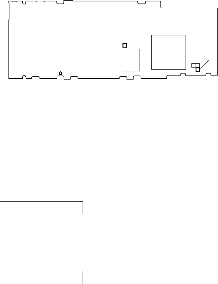
VDDCORE voltage : 1.8 to 2.0 V (voltage between TP9002 (VDDCORE) and TP (GND))
VDDIO2 voltage : 2.7 to 2.9 V (voltage between TP9003 (VDDIO2) and TP (GND))
Consumed electric current : below 200 mA
Connecting Location:
3-2. Writing destination
Note: When the displayed destination is correct, writing destination is no needed. But when the EEPROM check is performed, leave the display as it is and
press the [DISPLAY] key to perform this check.
After replacing the EEPROM, make it sure to write destination.
Every time the [MEGA BASS] key is pressed, the display changes as t “JP t US t EU t X t JP t...”.
Select the destination*, and press the [DISPLAY] key to fix. Then the LCD display changes from blinking to being on. Also at the same
time, checking destination written on the EEPROM is performed, and when the result is OK, the LCD back light turns on, and if not, starts
blinking.
*) JP : Japanese model EU : AEP, UK, E, Hong Kong, Korean, Chinese models
US : US model X : French model
4. Checking the Rated Voltage
Note: Before entering this mode, check that the input voltage is the specified value (1.23 V).
Press the [MENU] key after “3-2. Writing Destination” to enter this mode. The check is started automatically.
When the result is OK, “1. HLFBT >OK” is displayed on the LCD. And if the result is NG, “1. HLFBT >NG” is displayed.
5. Checking LOW BATT Voltage
Note: Before entering this mode, adjust the input voltage to the LOW BATT voltage value (0.95 V).
Press the [MENU] key after “4. Checking the rated voltage” to enter this mode. The check is started automatically.
When the result is OK, “2. LOWBT >OK” is displayed on the LCD. And if the result is NG, “2. LOWBT >NG” is displayed.
Press the [MENU] key to go to the next USB self-check.
TP9003
(VDDIO2)
IC8000
IC5000
TP9002
(VDDCORE)
TP (GND)
– MAIN BOARD (Conductor Side) –
1.HLFBT >
display
2.LOWBT >
display
