


6
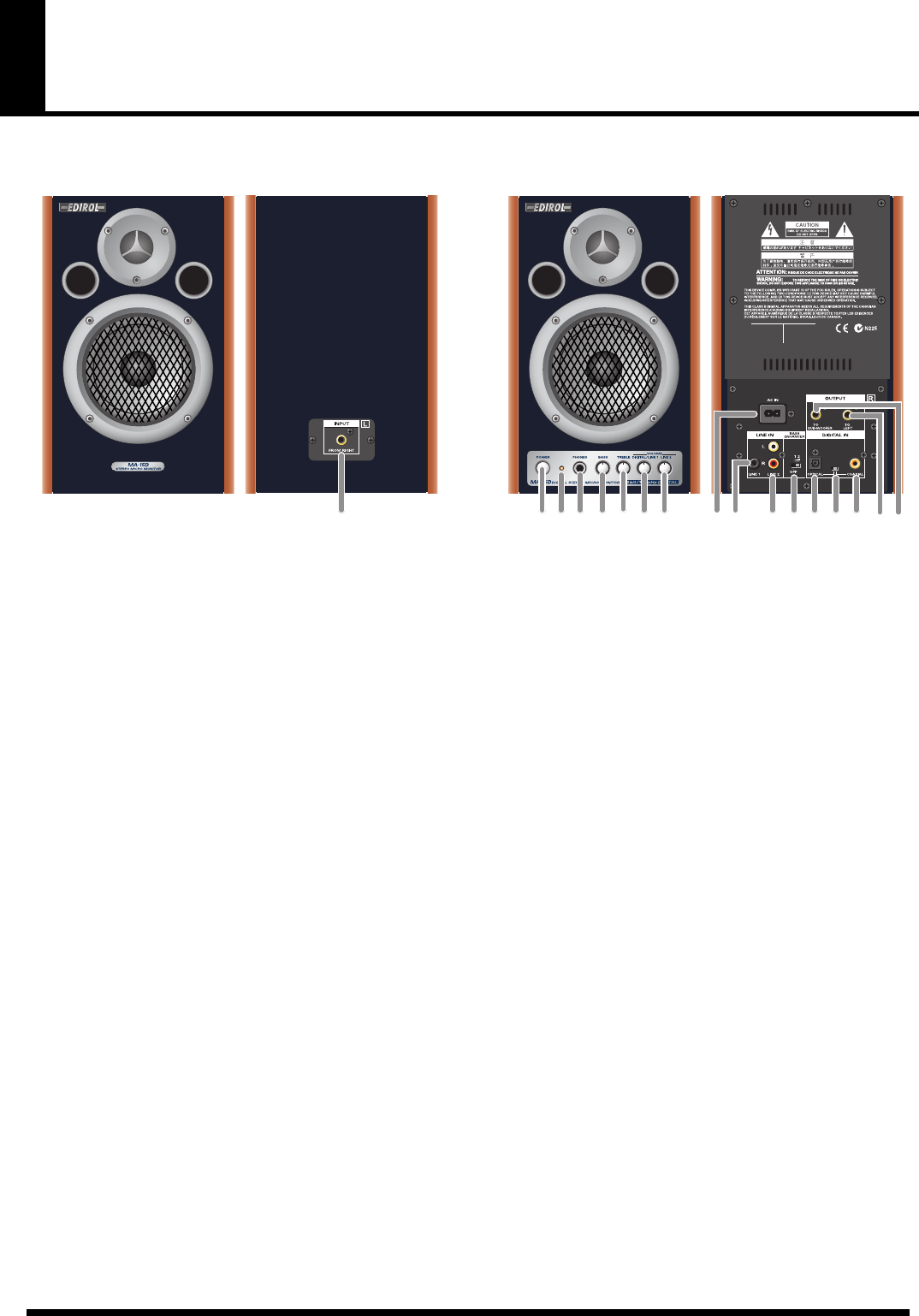
Panel Description
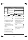
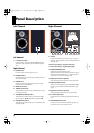
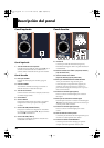
Left Channel
fig.2
Left Channel
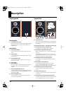
1.
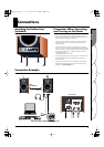
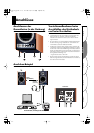
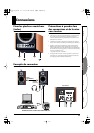
L Channel Input Jack
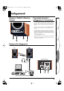
Connect this to L Channel Output Jack
16
on the right-
side unit. For the connection, use the included speaker
cable.
Right Channel
2.
POWER Switch
Press this switch to turn the power on/off.
3.
POWER Indicator
When the power is on, the indicator located at the side of
the switch will light.
4.
PHONES Jack
When you connect headphones to this jack, no sound
will be heard from the speakers.
5.
BASS Control Knob
6.
TREBLE Control Knob
These adjust the tones of the bass and treble. Set to center
to make the tones flat.
7.
VOLUME Knob (DIGITAL/LINE 1)
This adjusts the volume of devices connected to digital
input connectors
13
,
15
, and LINE 1 Input Jacks
10
.
8.
VOLUME Knob (LINE 2)
This adjusts the volume of the device connected to LINE
2 Input Jacks
11
.
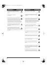
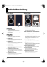
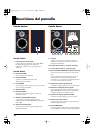
Right Channel
fig.3
9.
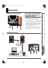
AC Inlet
Connect the included Power cord here (p. 17). Plug it
firmly in, so that the cable does not accidentally become
disconnected.
10.
LINE 1 Input Jacks (L, R) (stereo mini type)
11.
LINE 2 Input Jacks (L, R) (RCA phono type)
12.
BASS ENHANCER Switch
Switch this on to boost the bass range.
With the switch in the OFF position, sounds are output
without the effect applied. Set to “1” to boost the bass
range or to “2” for an even stronger effect.
13.
Digital Input Connector (Optical)
This is the digital input connector for optic-fiber cable.
14.
Digital Input Select Switch
This switch selects digital input connector
13
or
15
on
the rear panel. Select the connector used for the input
signal.
15.
Digital Input Connector (Coaxial)
This is the digital input connector for coaxial cable.
16.
L Channel Output Jack
Connect this to L Channel Input Jack
1
on the left-side
unit.
17.
SUB-WOOFER Output Jack
Connect your sub-woofer here. Obtain separately any
sub-woofer you wish to connect and use.
1
2 3 4 5
6
7 8
10 11 12 13 14 15 16 17
9
MA-15D_egfis.fm 6ページ 2005年10月31日 月曜日 午後7時16分