


July 1992 8
Philips Semiconductors Preliminary specification
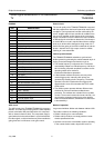
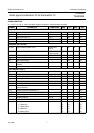
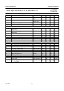
Small signal combination IC for black/white TV
TDA8303
TDA8303A
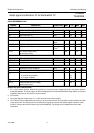
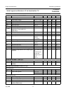
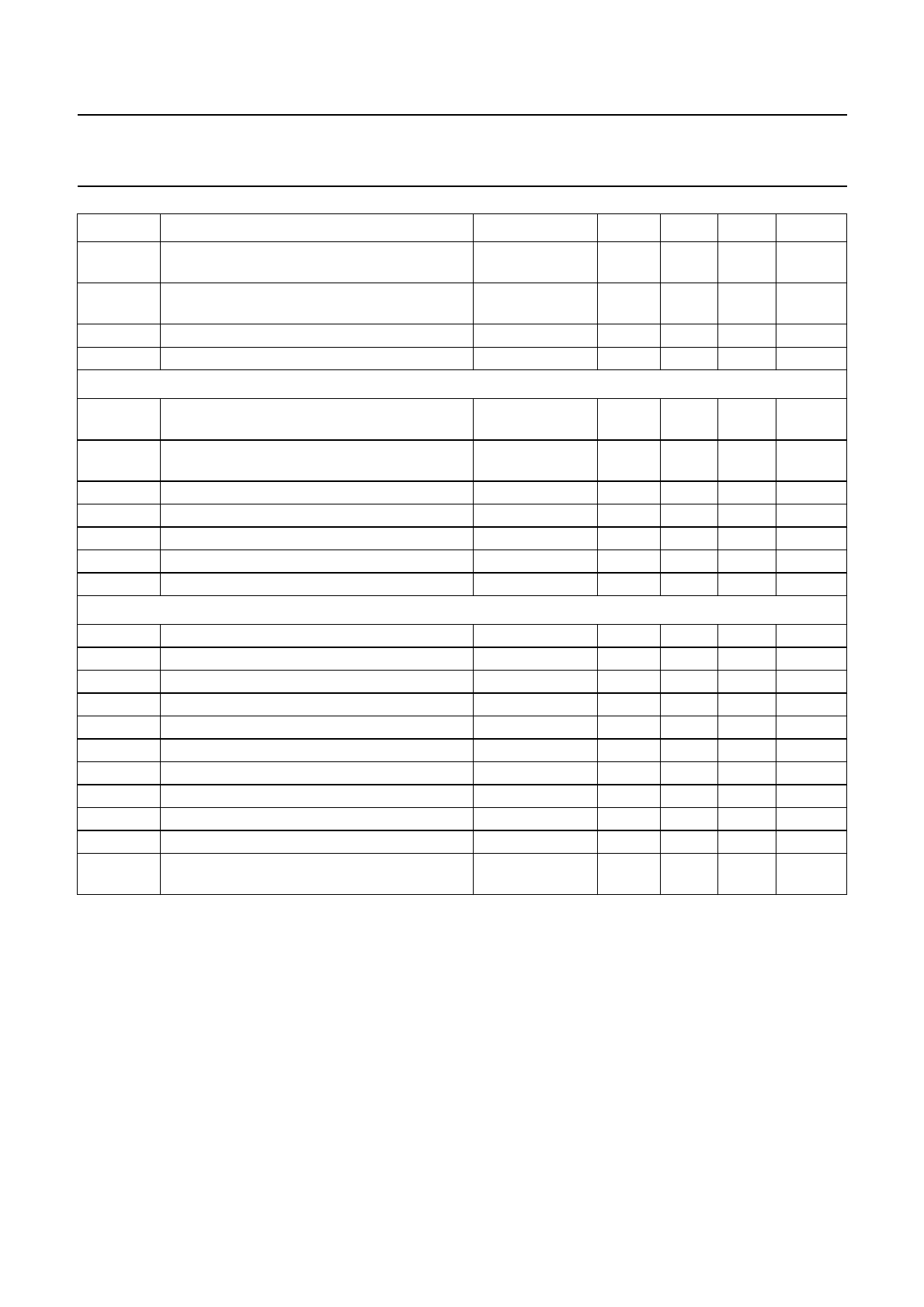
S/N signal-to-noise ratio 10 mV input
signal
50 57 − dB
S/N signal-to-noise ratio end of gain
control range
50 62 − dB
V
17
residual carrier signal − 210mV
V
17
residual 2nd harmonic of carrier signal − 210mV
Tuner AGC
V
8-9(RMS)
minimum starting point for tuner take−over
(RMS value)
−−0.2 mV
V
8-9(RMS)
maximum starting point for tuner take−over
(RMS value)
100 150 − mV
I
5
maximum tuner AGC output swing V
5
= 3 V 4 −−mA
V
5
output saturation voltage I
5
= 2 mA −−300 mV
I
L
leakage current (pin 5) −−1µA
∆V
I
input signal variation complete tuner control 0.2 2 4 dB
V
1
minimum voltage tuner take−over −−1V
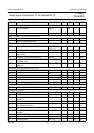
AFC circuit
I
19
AFC sample-and-hold switch-off current 0.1 −−mA
I
O
output current (pin 19) V
19
= 0 V − 0.1 0.3 mA
I
LO
output leakage current (pin 19) −−2µA
V
18
AFC output voltage swing notes 18 and 19 10.5 − 11.5 V
I
18
available output current 0.2 −−mA
control slope − 100 − mV/kHz
V
O
output voltage (pin 18) AFC off 5.5 6 6.5 V
R
O
AFC output resistance − 40 − kΩ
V
18
output voltage swing notes 25 and 26 − 11 − V
control slope notes 25 and 26 − 80 − mV/kHz
V
18
output voltage shift with respect to
V
I
= 10 mV(RMS)
notes 25 and 26 −−2−V
SYMBOL PARAMETER CONDITIONS MIN. TYP. MAX. UNIT