


July 1992 3
Philips Semiconductors Preliminary specification
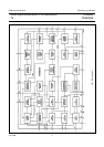
Small signal combination IC for black/white TV
TDA8303
TDA8303A
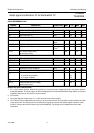
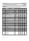
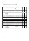
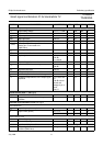
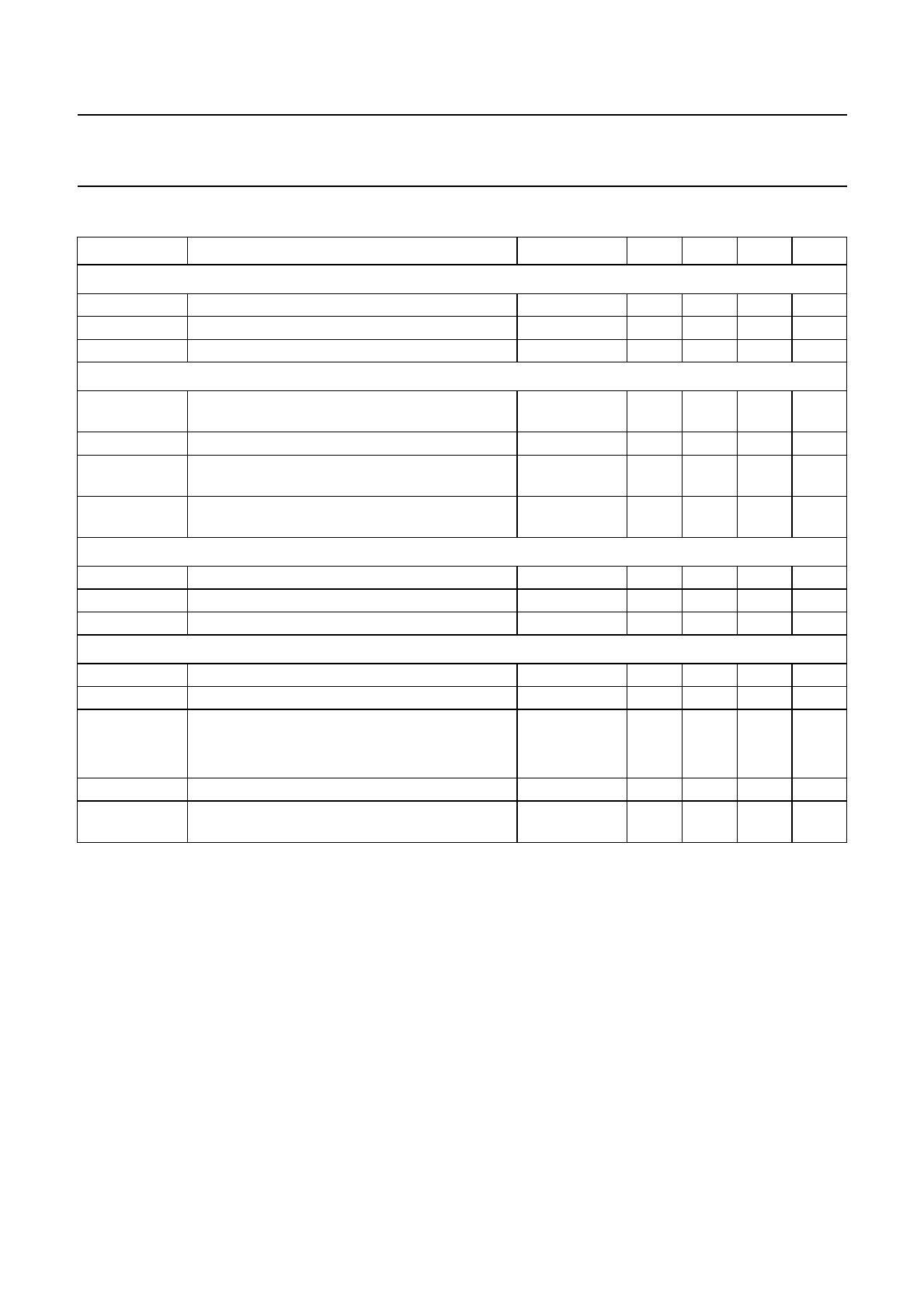
QUICK REFERENCE DATA
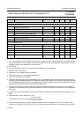
Notes to the quick reference data
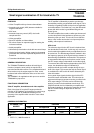
1. Pin 11 has a double function. When during switch-on a current of 9 mA is supplied to this pin, it is used to start the
horizontal oscillator. The main supply can then be obtained from the horizontal deflection stage. When no current is
supplied to this pin it can be used as a volume control.
2. On set AGC.
3. The output signal is measured at ∆f = 7.5 kHz and maximum volume control.
4. The minimum value is obtained by connecting a 1.8 kΩ resistor and a 470 nF capacitor in series between the video
output and pin 25. The slicing level can be varied by changing the value of this resistor (higher resistance value
results in a larger value of the minimum sync pulse amplitude). The slicing level is independent of the video
information.
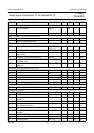
SYMBOL PARAMETER CONDITIONS MIN. TYP. MAX. UNIT
Supply
V
P
positive supply voltage (pin 7) 9.5 12 13.2 V
I
P
supply current (pin 7) 90 125 160 mA
I
start
start current (pin 11) note 1 − 6.5 9 mA
Video
V
8-9(RMS)
IF sensitivity (RMS value) at 38.9 MHz;
note 2
20 40 65 µV
G
8-9
IF gain control range − 74 − dB
S/N signal-to-noise ratio input signal =
10 mV
− 57 − dB
V
18(p-p)
AFC output voltage swing
(peak-to-peak value)
10.5 − 11.5 V
Sound
V
12(RMS)
AF output signal (RMS value) note 3 400 600 800 mV
AMS AM suppression at V
I
= 50 mV − 58 − dB
THD total harmonic distortion − 0.5 − %
Sync
V
25
required sync pulse amplitude note 4 200 −−mV
I
27
required input current during flyback pulse 0.1 − 2mA
V
22
coincidence detector output voltage
in synchronized condition − 9.7 − V
in no signal condition − 1.5 − V
V
22
vertical feedback for DC voltage 2.9 3.3 3.7 V
V
22(p-p)
vertical feedback for AC voltage
(peak-to-peak value)
− 1.2 − V