


July 1992 10
Philips Semiconductors Preliminary specification
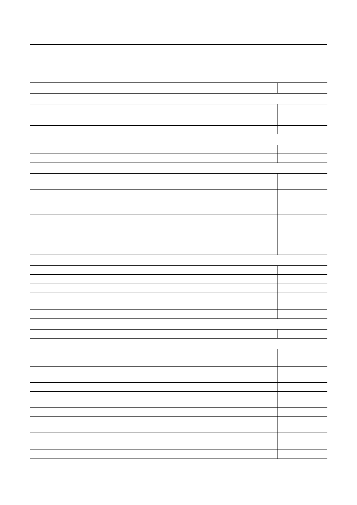
Small signal combination IC for black/white TV
TDA8303
TDA8303A
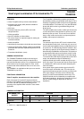
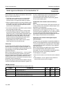
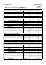
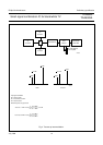
SECOND CONTROL LOOP (POSITIVE EDGE)
control sensitivity note 22 − 100 −
t
d
control range − 25 −µs
PHASE ADJUSTMENT (VIA SECOND CONTROL LOOP)
control sensitivity − 25 −µA/µs
α maximum allowed phase shift −±2−µs
H
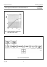
ORIZONTAL OSCILLATOR
f
fr
free running frequency R = 34.3 kΩ;
C = 2.7 nF
− 15625 − Hz
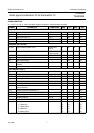
∆f spread with fixed external components −−4%
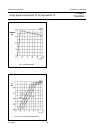
∆f
fr
frequency variations with supply voltage from
9.5 to 13.2 V
−−2%
∆f
T
frequency variation with temperature note 25 −−1.6 − Hz/°C
∆f
fr
maximum frequency deviation at start of
horizontal output
−−10 %
∆f frequency variation when only noise is
received
note 25 −−500 Hz
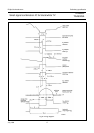
H
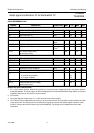
ORIZONTAL OUTPUT (PIN 26; OPEN COLLECTOR)
V
26
output limiting voltage −−16.5 V
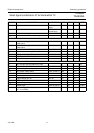
V
OL
LOW level output voltage I
sink
= 10 mA − 0.2 0.5 V
I
sink
maximum sink current 10 −−mA
duty factor of output signal − 46 − %
t
r
rise time of output pulse − 260 − ns
t
f
fall time of output pulse − 100 − ns
HORIZONTAL FLYBACK INPUT (PIN 27)
I
27
required input current during flyback pulse 0.01 − 1.0 mA
COINCIDENCE DETECTOR
V
22
voltage for in-sync condition − 9.8 − V
V
22
voltage for no-sync condition no signal − 1.5 − V
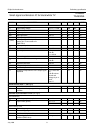
V
22
switching level to the phase detector from fast
to slow
6.2 6.7 7.2 V
V
22
hysteresis slow to fast − 0.6 − V
V
22
switching level to activate the mute function
(transmitter identification)
2.5 2.8 3.1 V
V
22
hysteresis mute function − 2 − V
t
d
delay of mute release after transmitter
insertion
−−300 µs
allowable load on pin 22 −−10 µA
V
22
external video mode −−0.7 V
I
22
current at pin 22 V
22
= 0 V −−0.8 mA
SYMBOL PARAMETER CONDITIONS MIN. TYP. MAX. UNIT
δt
d
δt
o
-------