


20
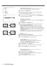
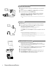
Connect Accessory Devices
There is a wide range of audio and video devices that can be connected to
your TV.The following connection diagrams show you how to connect them.
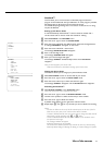
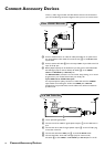
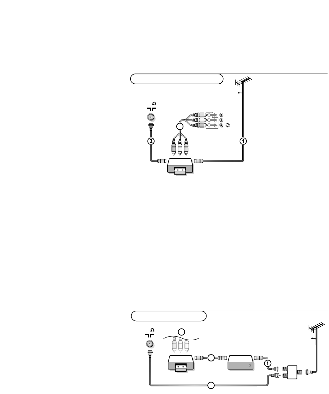
& Connect the RF Antenna or Cable TV cable (eventually via an optional two-
way signal splitter and/or Cable TV converter box)
1 to the RF IN socket
of your VCR.
é Connect another RF cable 2 from the output OUT of your VCR to the TV’s
input 75
Ω x jack.
“ Better playback quality can be obtained if you also connect the Video,Audio
Left and Right (only for stereo devices) AV cables
3 to the VIDEO,
L/Mono and R AUDIO input AV2 IN jacks.
The
MONITOR OUT connectors can be used for daisy chaining or to record
programs from your TV. See Record with your VCR, p. 29.
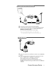
If your VCR has an S-VHS video jack:
For improved picture quality, connect an S-video cable with the S-VIDEO
input instead of connecting the VCR to the VIDEO jack of AV2 IN.
S-Video does not provide audio, so audio cables must still be connected to
provide sound.
CABLE
VCR
OUT
OUT IN
AV 2
in
AV 1
in
Monitor
out
COMPONENT VIDEO INPUT
VIDEO
L/Mono
R
Y
Pb
Pr
AUDIO
S-VIDEO
3
75
CABLE
VCR
Cable Box
3
2
OUT
OUT IN OUT IN
75
SIGNAL
SPLITTER
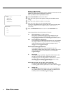
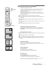
4
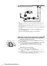
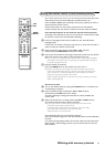
& Use an optional signal splitter
é Connect one of the cable TV signal splitter outputs 1 to the cable box’s in
jack.
“ Connect the other cable TV signal splitter output 2 to the 75 Ω x plug
on the back of the TV.
‘ Connect the cable box’s OUT jack 3 to the VCR’s RF IN socket.
( Connect the Video, Audio Left and Right (only for stereo sound)
AV cables
4 to the VIDEO, L and R AUDIO input AV2 IN jacks on the TV.
VCR and Cable Box
Video Cassette Recorder
Connect Accessory Devices