


Host card back panel connectors and pinouts
Page 36
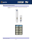
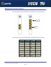
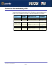
RJ45 back panel connectors and pinout
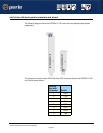
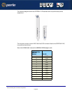
The following diagram shows the SPEED2 LE and SPEED4 LE RJ-45 cards back panel.
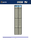
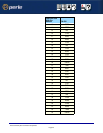
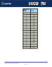
The connector pinout for each RJ45 socket fitted to the SPEED LE cards are as follows;
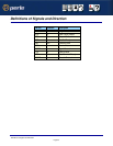
RJ45 10-pin RJ45 8-pin EIA-232 DIRECTION
1 N/A RI IN
2 1 DCD IN
3 2 DTR OUT
4 3 DSR IN
5 4 GND
6 5 TXD OUT
7 6 RXD IN
8 7 RTS OUT
9 8 CTS IN
10 N/A
Shell Shell C-GND