


6 C579M-A (5/05)
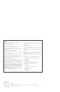
e. Reinstall the top cover and secure with mounting screws.
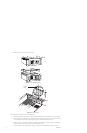
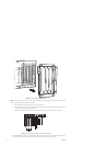
Figure 2.
Removing the CC1 Top Cover
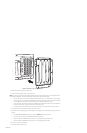
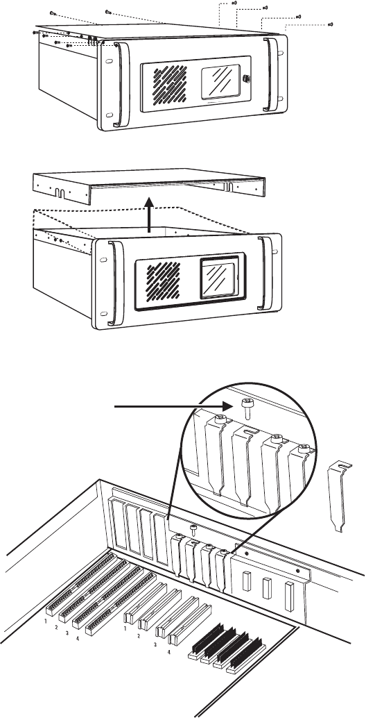
Figure 3.
CC1 Internal Layout
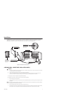
3. Mount external hardware. Refer to Figure 1 and do the following:
a. Mount the port expansion unit so that the two supplied data cables will reach the CC1 unit. The data cables are three feet in length.
b. Connect the male end of one data cable to the bottom DB26 connector of the RP card installed in the CC1. Connect the other (female)
end to the DB25 host connector for the second grouping of 16 ports on the right side of the port expansion unit.
c. Connect the male end of the remaining data cable to the top DB26 connector of the RP card. Connect the other end to the DB25 host
connector for the first grouping of 16 ports on the left side of the port expansion unit.
d. If using RS-232 operation, set the switch located to the right of each port used on the port expansion unit to the “232” position.
ISA
SLOTS
PCI
EXPANSION
SLOTS
COVER
RETAINING
SCREW