12 C579M-A (5/05)
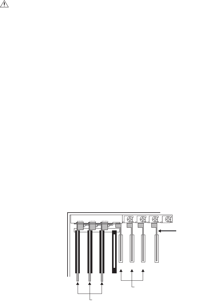
3 SERCOM CARDS, 3 ROCKET PORT CARDS, COM 2 UNAVAILABLE (120 TOTAL PORTS)
1. Turn off all power to the CC1. Disconnect and label all attached cabling.
2. Remove the top cover mounting screws (refer to Figure 2).
3. From the rear, tilt the top cover up at a slight angle, and then pull backwards away from the front edge to remove the cover from the CC1
chassis (refer to Figure 2).
4. Install the RP cards into the CC1.
a. Remove the screws securing the Sercom card mounting plate (refer to Figure 5).
b. Remove the Sercom card mounting plate by gently pulling outward from the CC1 chassis (refer to Figure 5).
c. Remove the Sercom card from ISA slot 4 by gently pulling up (refer to Figure 3).
NOTE:
This configuration mandates that the VGA card be installed in PCI slot 4. If present in any other PCI expansion slot, remove the retaining
screw and gently pull the card up. Reinstall the card into PCI slot 4 (follow steps d, e, and f, applying them to the VGA card and PCI slot 4).
d. Remove the retaining screw and slot cover for PCI slot 2 and 3. Slide both covers out.
e. Install an RP card into PCI slot 1. Carefully align the gold-fingered edge connector of the RP card with the PCI slot. Gently but firmly
press RP card down until fully seated into the PCI slot.
f. Repeat step e for installing the second and third RP cards into PCI slots 2 and 3. Reinstall the retaining screws to secure these RP
cards into place.
Figure 8.
Sercom/PCI Card Configuration for 120 Ports, Com 2 Unavailable
5. Install the CM9700-ADP-120 adapter plate. Carefully align the plate with the front of the three Sercom cards and the RP card in PCI slot 1
while pushing in toward the CC1 chassis. Secure with mounting plate screws removed earlier. Refer to Figure 7.
6. Reinstall the top cover and secure with mounting screws.
WARNING:
•
Software version 9.03.007 or higher must be installed in the CC1 to enable port expansion ability. If running a previous version, contact Pelco
for software upgrade kit options and availability.
•
Failure to turn off the CC1 power could result in serious damage to the equipment.
•
Electrostatic discharge (ESD) precautions must be observed when performing the procedures described in this manual. Always wear a
gounding strap connected to an approved grounding source when working on or around exposed electronic components.
12
3
4
RP CARDS
SERCOM
CARDS
VGA CARD


