


Jumper JP3: 75 Ohm RX Shield to 120 Ohm Overall Shield
In the default “Connected” setting, the 75 Ohm receive in coaxial
shield connects to RJ-45 pin 6, the receive pair shield.
JP3 Setting Description
Position 1 & 2 Connected 75 Ohm RX shield
connected to the RJ-45
overall foil shield
Position 2 & 3 Not Connected 75 Ohm RX shield not
connected to the RJ-45
overall foil shield
Jumper JP4: 75 Ohm RX Shield to 120 Ohm Rx Pair Shield (Pin 6)
In the default “Connected” setting, the 75 Ohm coaxial shield
connects to the RJ-45 overall foil shield.
JP4 Setting Description
Position 1 & 2 Not Connected 75 Ohm RX shield not
connected to the RJ-45
RX pair shield (Pin 6)
Position 2 & 3 Connected 75 Ohm RX shield
connected to the RJ-45
RX pair shield (Pin 6)
Jumper JP7: RJ-45 Shield to Chassis Ground
In the default “Connected” setting, the RJ-45 overall shield
connects to chassis ground.
JP7 Setting Description
Position 1 & 2 Connected RJ-45 shield connects
to Frame Ground.
Position 2 & 3 Not Connected RJ-45 shield does not
connect to Frame
Ground.
5 6
4.0 INSTALLATION
This section describes the functions of the Model 460RC16 rack
chassis, tells how to install front and rear Model 460RC/F Series cards
into the chassis, and how to connect to the twisted pair interface and
the serial interface.
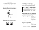
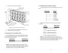
4.1 THE MODEL 460R16 RACK CHASSIS
The Model 460R16 Rack Chassis (Figure 3, below) can
accomodate up to 16 G.703 75 Ohm coax to 120 Ohm RJ-45 baluns.
Measuring only 3.5” high, the Model 460R16 is designed to occupy only
2U in a 19” rack. Sturdy front handles allow the Model 460R16 to be
extracted and transported conveniently.
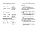
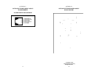
4.2 INSTALLING THE MODEL 460RC/F MODULE INTO THE
CHASSIS
The Model 460RC16 comprised of a 2U high rack chassis and
individually mountable G.703 balun modules. You may purchase a fully
populated 16 port rack or you may purchase individual modules. Refer
to Figure 4 as a guide and follow the steps below to install each Model
additional 460RC/F module into the rack chassis:
1. Slide the two star washers over the screws on each end of the
mount space.
2. Slide the Model 460RC/F pc board over the screws with the
BNC connectors facing downward. Then push the BNC
connectors and RJ-45 connector through the matching slots in
the front of the rack assembly.
3. Slide a plastic spacer over each screw to secure the pc board.
Figure 3. Fully Populated Model 460RC16 Rack Chassis