


3.1.1 Jumper Straps JP1, JP2, JP3, JP4, and JP7
The jumper straps allow you to set shielding and grounding options
for the Model 460RC/F. The settings for each jumper strap are shown
briefly in the table below. Following this table are more detailed
explanations of each jumper.
Jumper JP1: 75 Ohm TX Shield to 120 Ohm TX Pair Shield (Pin 3)
In the default “Connected” setting, the 75 Ohm transmit out coaxial
shield connects to RJ-45 pin 3, the transmit pair shield.
JP1 Setting Description
Position 1 & 2 Not Connected 75 Ohm TX shield not
connected to RJ-45 TX
pair shield (Pin 3).
Position 2 & 3 Connected 75 Ohm TX shield
connected to RJ-45 TX
pair shield (Pin 3).
Jumper JP2: 75 Ohm Shield to 120 Ohm Overall Shield
In the default “Connected” setting, the 75 Ohm transmit out coaxial
shield connects to the RJ-45 overall foil shield.
JP2 Setting Description
Position 1 & 2 Connected 75 Ohm TX shield
connected to the RJ-45
overall foil shield.
Position 2 & 3 Not Connected 75 Ohm TX shield not
connected to the RJ-45
overall foil shield.
4
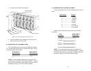
3.0 CONFIGURATION
Each Model 460RC/F Module is equipped with four jumpers that
you may use to configure several grounding options. This section
shows the jumper locations and describes their functions.
3.1 SETTING THE JUMPER STRAPS
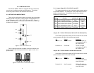
There are five configuration jumpers on the back side of the Model
460RC/F printed circuit board. These jumpers are labeled below and
on the PC board as “JP1”, “JP2”, “JP3”, “JP4”, and “JP7”. Figure 1,
below, shows their positions on the pc board as well as the relative pin
numbers on the jumpers.
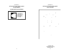
Figure 2 (below) shows the orientation of the rear interface card
straps. Observe that the strap can either be on posts 1 and 2, or on
posts 2 and 3.
3
Figure 1. Individual Model 460RC/F Card
1
2
3
1
2
3
1
2
3
1
2
3
1
2
3
JP3
JP4
JP7
JP2
JP1
Figure 2. Possible Positions for Model 460RC/F Jumpers
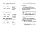
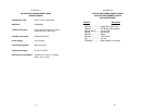
INTERFACE CARD STRAP SUMMARY TABLE #1
Strap Function Position 1&2 Position 2&3
JP1 Coax TX Shield & RJ45 Pin 3 Open* Connected
JP2 Coax TX Shield & RJ-45 Shield Connected* Open
JP3 Coax RX Shield & RJ-45 Shield Connected* Open
JP4 Coax RX Shield & RJ-45 Pin 6 Open* Connected
JP7 RJ-45 Shield & Chassis Ground Connected* Open
* Indicates default setting