MODEL 110 AUTORANGING DIGITAL MULTIMETER
5
4.0 Control Functions:
4.1 Function Selector Rotary Switch
The rotary switch turns power on to the instrument and selects the
function to be measured. The functions available and their
specifications are detailed in Section 2.0.
4.2 Range Selection
In all functions except
(Diode Test) and A (AC or DC
Current), the instrument powers on in the Autoranging mode and
the AUTO symbol appears in the display. To select a range
manually, press the ‘Range’ button. The Manual Range symbol
will appear in the display, and the instrument will then be locked in
the range selected. When in the Manual mode, each successive
press of the ‘Range’ button increases the measurement range.
Range selection loops back to the lowest range when advanced
from the highest range. To exit the Manual mode, press and hold
the ‘Range’ button for one second or rotate the Function Selector
switch to a different measurement function, and the instrument
returns to the Autoranging mode.
4.3 Relative Operation
Pressing the UREL button zeroes the display and internally
stores the present reading as a reference for subsequent
measurements. The main display now shows the difference
between the stored value and the new reading. Press and hold
the UREL for one second to exit the Relative mode.
4.4 MAX/MIN Operation
Press the MAX MIN button to enter the MAX/MIN mode. In this
mode, both the maximum and minimum values are
simultaneously retained in memory and updated with every new
data sample. The instrument first enters the MAX mode, and the
MAX symbol and value are both displayed. Pressing MAX MIN
again advances the display to the MIN symbol and value. The
next press of the MAX MIN button will cause both the MAX and
MIN symbols to flash. This indicates that the maximum and
minimum values have been updated in memory and the displayed
MODEL 110 AUTORANGING DIGITAL MULTIMETER
10
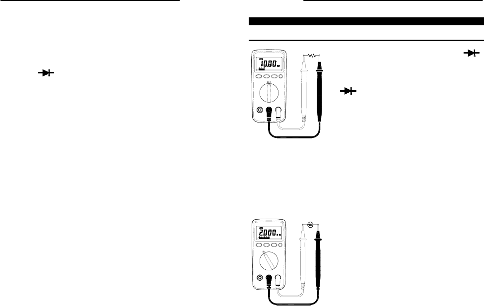
5.6 Diode Tests
WARNING!
Before making any in-circuit measurements, remove power from the circuit being
tested and discharge all capacitors in the circuit.
1. Connect the red test lead to the
‘ ’
jack and the black test lead to the
‘COM’
jack.
2. Set the Function Selector switch to the
range.
3. Remove power from the circuit being
tested and discharge all capacitors in
the circuit.
4. Connect the red test lead to the anode
side and the black test lead to the
cathode side of the diode being tested.
5. Read the Forward Voltage (V
f
) on the
instrument display.
Note: If the polarity of the test leads is reversed, the display will
read ‘OL’. This can be used to determine the anode and
cathode terminals of a diode.
5.7 Frequency Measurements
1. Connect the red test lead to the
‘Hz’
jack
and the black test lead to the
‘COM’
jack.
2. Set the Function Selector switch to the
Hz range.
3. Connect the test leads in parallel with
the circuit being measured.
4. Read the frequency on the instrument
display.


