


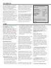
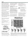
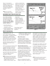
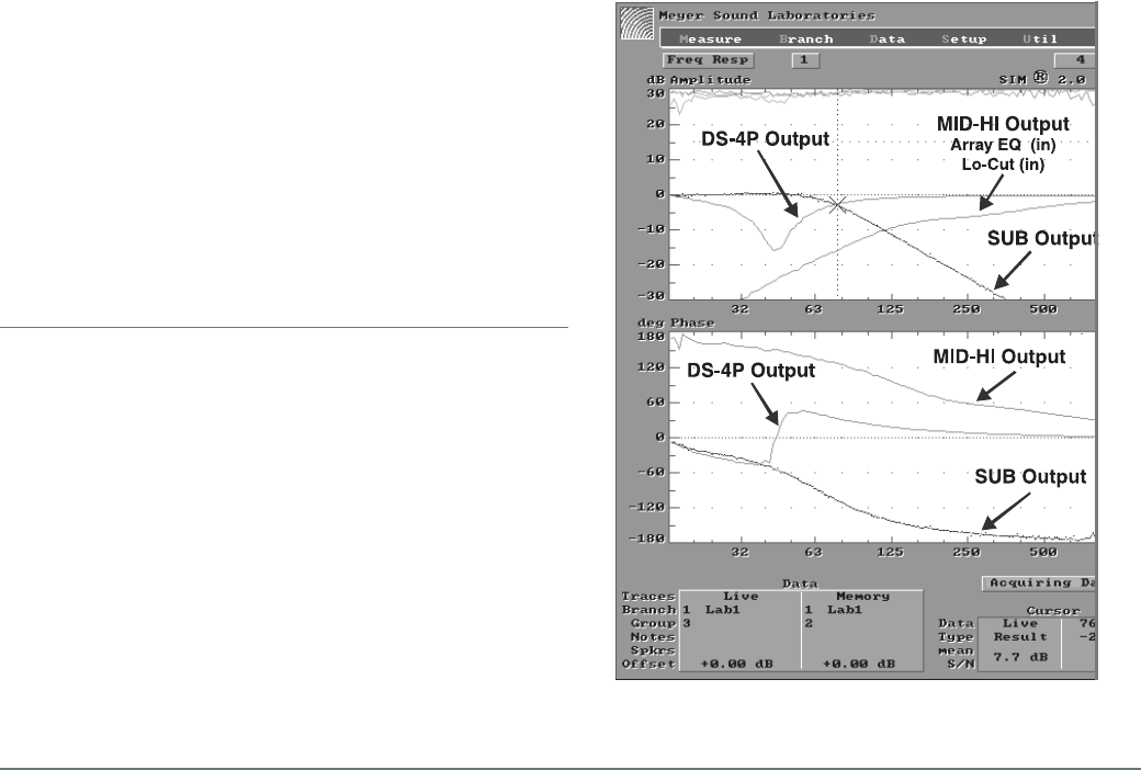
Figure 2 is the electrical
response of the LD-1A with all
three filters engaged, and
polarity options equal (non-
inverted) as recommended in
the previous (Figure 1)
diagram.
NOTE: The LD-1A’s DS-2P
output provides a special
eq filter to minimize time
offset in the VLF range. The
Sub Output as well as the
Hi-Pass filter are gentle
slopes (about 12 dB per
octave) in order to
minimize time offset of all
three products working
together through the 30 to
200 Hz passband.
9
Figure 2
MEASUREMENT AND SYSTEMS INTEGRATION TOOLS
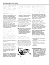
It is essential that even the
most carefully assembled
sound systems be analyzed
with precise measurement
tools. We recommend using
the Meyer Sound SIM® System
II Sound Analyzer and CP-10
Parametric Equalizer to
• assist the process of
choosing and configuring
loudspeaker systems;
• measure propagation delays
between subsystems to set
the correct polarity and
delay times;
• measure and equalize
variations in frequency
response caused by the
acoustical environment and
the placement and
interaction of loudspeaker
systems.
Contact Meyer Sound for
assistance with your
application.
TROUBLESHOOTING WITH TPL
The TPL LED can indicate potential
driver problems, if interpreted correctly.
If one DS-4P in a system exhibits
substantially more TPL activity than
others receiving the same audio signal,
then one or both drivers in that unit
may have a short circuit. This is a
potentially dangerous condition for the
electronics; shut the DS-4P down
immediately.
The TPL circuit does not activate if there
is no power dissipation in the driver,
regardless of the input signal level.
Therefore, if all DS-4Ps in a system
receiving the same audio signal exhibit
TPL activity except one, then that unit
may have an open voice coil; disconnect
it and contact Meyer Sound for
replacement information.
NOTE: The Remote Monitoring System
(RMS) provides precise information
about peak power, peak voltage, and
average voltage (VU) for each
amplifier channel, enabling a more
complete driver diagnostic than the
TPL LEDs. Contact Meyer Sound for
more information about RMS.
DRIVER REPLACEMENT
To determine whether a driver is
functioning properly, or replace a
damaged driver, contact Meyer Sound to
obtain the Low Driver Inspection and
Evaluation Procedure for Self-Powered
Series Products (part # 17.033.120.01).
VERIFYING DRIVER POLARITY
Incorrect driver polarity impairs system
performance and may damage the
drivers. All Meyer Sound loudspeakers
are shipped with the drivers in correct
alignment. However, if the driver or
circuit wiring has been removed or
disassembled in any loudspeaker in a
system for any reason, it is essential to
check the polarity between drivers in
the same cabinet and between adjacent
loudspeakers.
We do not recommend using phase
poppers to analyze driver polarity. The
phase response for all drivers varies, to
some degree, over the frequency range
in which it operates. Since the phase
popper, a popular but inaccurate tool,
does not discern variations in phase
response with respect to frequency, it
provides no useful information about the
phase response through the crossover,
the most important consideration for
determining correct driver polarity.
Phase poppers are, therefore, not useful
for performing phase measurements on
an individual loudspeaker or a full-range
sound system containing one or more
crossovers. If necessary, apply a phase
popper only to loudspeakers with
identical drivers without a crossover, and
check the system’s overall phase
response with a frequency analyzer
and/or listening test.
NOTE: Since polarity reversal causes ex-
cessive driver excursion at high
source levels, use moderate levels for
these tests.
DRIVER TROUBLESHOOTING