


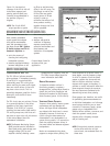

DRIVER POLARITY IN THE SAME
LOUDSPEAKER
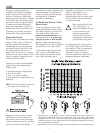
Use the following test procedure to
verify polarity between drivers in the
same loudspeaker:
1. Place a measurement microphone 3 ft
from the front of the loudspeaker at
the midway point between the two
drivers.
2. Connect a signal source to the loud-
speaker and note the frequency
response.
The polarity is correct if the frequency
response is ±4dB 50–160 Hz. Can-
cellation greater than 6 dB in the same
range indicates polarity reversal.
POLARITY BETWEEN ADJACENT
LOUDSPEAKERS
Use the following test procedure to
verify the polarity between adjacent
loudspeakers of the same type:
1. Position two loudspeakers adjacent to
each other.
2. Place a measurement microphone 3 ft
from the speakers on the axis
between them.
3. Connect a signal source to one loud-
speaker and note the frequency
response and overall level.
4. Apply the same signal to the second
loudspeaker with the first loudspeaker
still connected.
The polarity is correct if the frequency
response remains constant with a
significant increase in amplitude.
Broadband cancellation (decreased
overall level) indicates polarity reversal.
NOTE: Do not attempt to check more
than two adjacent loudspeakers in
one test. Detecting polarity reversal
among more than two loudspeakers is
difficult and may damage the drivers
in the cabinet with reversed polarity.
10
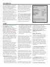
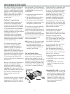
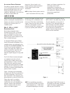
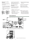
CONTROLS AND CONNECTORS
UU
LL
CC
UU
LL
®®
LISTED
3K59
COMMERCIAL
AUDIO SYSTEM
ATENCIÓN: ACCESO INTERNO S
A PERSONAL TÉCNICO CALIFICADO
ACHTUNG: GEHÄUSE NICH
WARTUNG UND REPARATUR
ELEKTROFACHKRÄFTE
ATTENTION: ENTRETIEN E
INTERNES NE SONT AUTORISEES
TECHNIQUE QUALIFIÉ
UK WARNING: THIS APPARAT
NO OPERATOR SERVICEABLE PARTS
SERVICING TO QUALIFIED PERSONNEL
WARNINGS:
This surface may reach high temperat
To ensure proper operation, allow a
clearance from this surface and adeq
To reduce the risk of electric shoc
No operator serviceable parts insid
qualified personnel.
To reduce the risk of fire or electric
this appliance to rain or moisture.
P
U
S
H
R
E
-
C
I
R
K
-
I
T
Pin 1 Earth / Chassis
Case Earth / Chassis
Input
Loop
Pin
2 +
3 +
!
1
1
2
3
1
3
2
8A RMS
20A Peak
95-125
~
50-60Hz
700W RMS MAX
Meyer Sound,
Auto-Voltage Select
Input Polarity
THIS PRODUCT MUST BE GROUNDED
P
U
S
H
R
E
-
C
I
R
K
-
I
T
PUSH
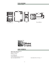
Made by:Meyer Sound,Berkeley,Ca. U.S.A.
European Office:
Meyer Sound Europe
14, Long Barn Lane,
Reading, Berkshire,
England RG2 7SZ
European User Panel with IEC 309 connector
Rear User Panel shown with the optional Remote Monitoring System (RMS) panel