


current during burst is used to select
the rating for fast-reacting magnetic
breakers and to calculate the peak
voltage drop in long AC cables according
to the formula
Vpk
drop
= Ipk x Rtotal cable
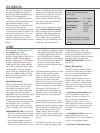
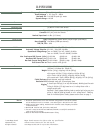
Use the table below as a guide to select
cables and circuit breakers with
appropriate ratings for your operating
voltage.
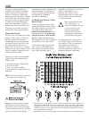
DS-4P Current Ratings
The minimum electrical service
amperage required by Meyer Sound
loudspeaker systems is the sum of their
maximum continuous RMS currents. We
recommend allowing an additional 30%
above the minimum amperage to
prevent peak voltage drops at the
service entry.
TROUBLESHOOTING NOTE: In the un-
likely case that the circuit breaker trips
(the white center buttons pop out), do
not reset the breaker! Contact Meyer
Sound for repair information.
SAFETY ISSUES
Pay close attention to these important
electrical and safety issues.
Use a power cord adapter to
drive the DS-4P from a
standard 3-prong outlet
(NEMA 5-15R; 125V max).
The DS-4P requires a grounded
outlet. Always use a grounding
adapter when connecting to
ungrounded outlets.
Do not use a ground-lifting
adapter or cut the AC cable
ground pin.
Keep all liquids away from
the DS-4P to avoid hazards
from electrical shock.
Do not operate the unit if
the power cables are frayed
or broken.
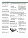
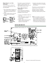
Tie-wrap anchors on the amplifier
chassis provide strain relief for the
power and signal cables. Insert the
plastic tie-wraps through the anchors
and wrap them around the cables.
POWER CONNECTOR WIRING
CONVENTIONS
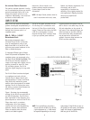
Use the following AC cable wiring
diagram to create international or
special-purpose power connectors:
AC cable color code
If the colors referred to in the diagram
don't correspond to the terminals in
your plug, use the following guidelines:
• Connect the blue wire to the terminal
marked with an N or colored black.
• Connect the brown wire to the
terminal marked with an L or colored
red.
• connect the green and yellow wire to
the terminal marked with an E or
or colored green or green and yellow.
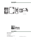
AUDIO INPUT
The DS-4P presents a 10 kOhm balanced
input impedance to a three-pin XLR
connector wired with the following
convention:
Pin 1 220 k to chassis and earth
ground (ESD clamped)
Pin 2 Signal
Pin 3 Signal
Case Earth (AC) ground and chassis
Shorting an input connector
pin to the case can form a
ground loop and cause hum.
Pins 2 and 3 carry the input as a
differential signal; their polarity can be
reversed with the input polarity switch
on the user panel. If the switch is in the
up position, pin 2 is hot relative to pin
3, resulting in a positive pressure wave
when a positive signal is applied to pin
2. Use standard audio cables with XLR
connectors for balanced signal sources.
TROUBLESHOOTING NOTE: If abnormal
noise (hum, hiss, popping) is
produced from the loudspeaker,
disconnect the audio source from the
loudspeaker. If the noise stops, then
the problem is not within the
loudspeaker; check the audio input
and AC power.
A single source can drive multiple DS-
4Ps with a paralleled input loop,
creating an unbuffered hardwired loop
connection. The input impedance for a
single DS-4P is 10k ; if n represents
the number of DS-4Ps in use, cascading
n DS-4Ps will produce a balanced input
impedance of 10k divided by n. To
avoid distortion from the source, make
sure that the source equipment can
drive the total load impedance
presented by the paralleled input
circuit. For most source equipment it is
safe to drive circuits whose input
impedance is no smaller than 10 times
its output impedance. For example,
cascading 10 DS-4Ps produces an input
impedance of 1000 Ohms (10k divided
by 10). The source equipment should
have an output impedance of 100 ohms
or less. This is also true when
connecting in parallel (loop out) DS-4Ps
to 650-Ps, MSL-4s, or any other Meyer
Sound self-powered loudspeaker system.
The LD-1A is highly recommended when
driving systems using multiple loudspeakers.
(See Complete Systems, page 8.)
5
V511
V032
V00
1
SMRsuounitnoC.xaMAAA
SMRtsruB.xaMAAA
tsruBgniruDkaePxaMAAA
8
4
10
15 8 18
22 11 25
brown = hot
blue =
neutral
yellow/green =
earth ground
(chassis)
Differential Outputs