


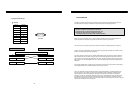
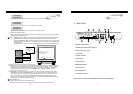
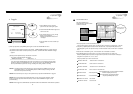
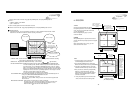
PANTILT COMMAND SETUP : When PTZ camera whose protocol is already incorporated into this DVMR
system (Default PTZ camera) is connected to this DVMR, just select model of PTZ camera in
PANTILT COMMAND SETUP. If user want to connect PTZ camera which is not one of Default PTZ
camera, users must input protocols of PTZ camera or speed dome camera by themselves in USER
DEFINE SETUP.
For detail procedure, refer to manual for incorporating protocol of PTZ camera into DVMR system.
HDD INFORMATION
5
4
HDD DATA LIST : Shows general information of HDD.
HDD AUTO DETECT : Allows to detect HDD just in case first HDD search after purchase failed.
5. Operation
27
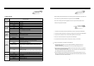
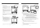
3. NOTE for scheduled recording :
When scheduled recording is set, DVMR unit does not record before the set time. It only starts recording at
01:00-03:00 ON
04:00-05:00 ON
Just record from 1 to 3 and from 4 to 5, and does not record for the rest hours.
01:00-03:00 OFF
04:00-05:00 OFF
Not record from 1 to 3 and from 4 to 5, and records for the rest hours.
01:00-03:00 ON
04:00-05:00 OFF
Just record from 1 to 3 (When both ON and OFF are set, priority is on ON.)
START time and ends at END time.
PANTILT COMMAND SETUP
SELECT , PRESS ENTER
COMMAND TYPE : USER DEFINE
485 BAUDRATE : 9600 BPS
USER DEFINE SETUP
1. DRX-502A
2. AECD-2000
3. HMC-250
4. PELCO D TYPE
3.USER DEFINE
SYSTEM SETUP
DISPLAY SETUP
CAMERA TITLE
TIME/DATE SETUP
ALARM/MOTION SETUP
RECORD SETUP
TCP/IP SETUP
MISCELLANEOUS
FACTORY DEFAULT
BUZZER SETUP
ID/PW SETUP
SCHEDULE REC
SETUP
PANTILT CMD SETUP
HDD INFORMATION
MARK IMAGE SETUP
PRODUCT ID
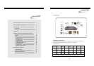
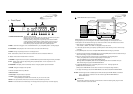
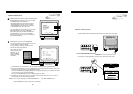
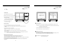
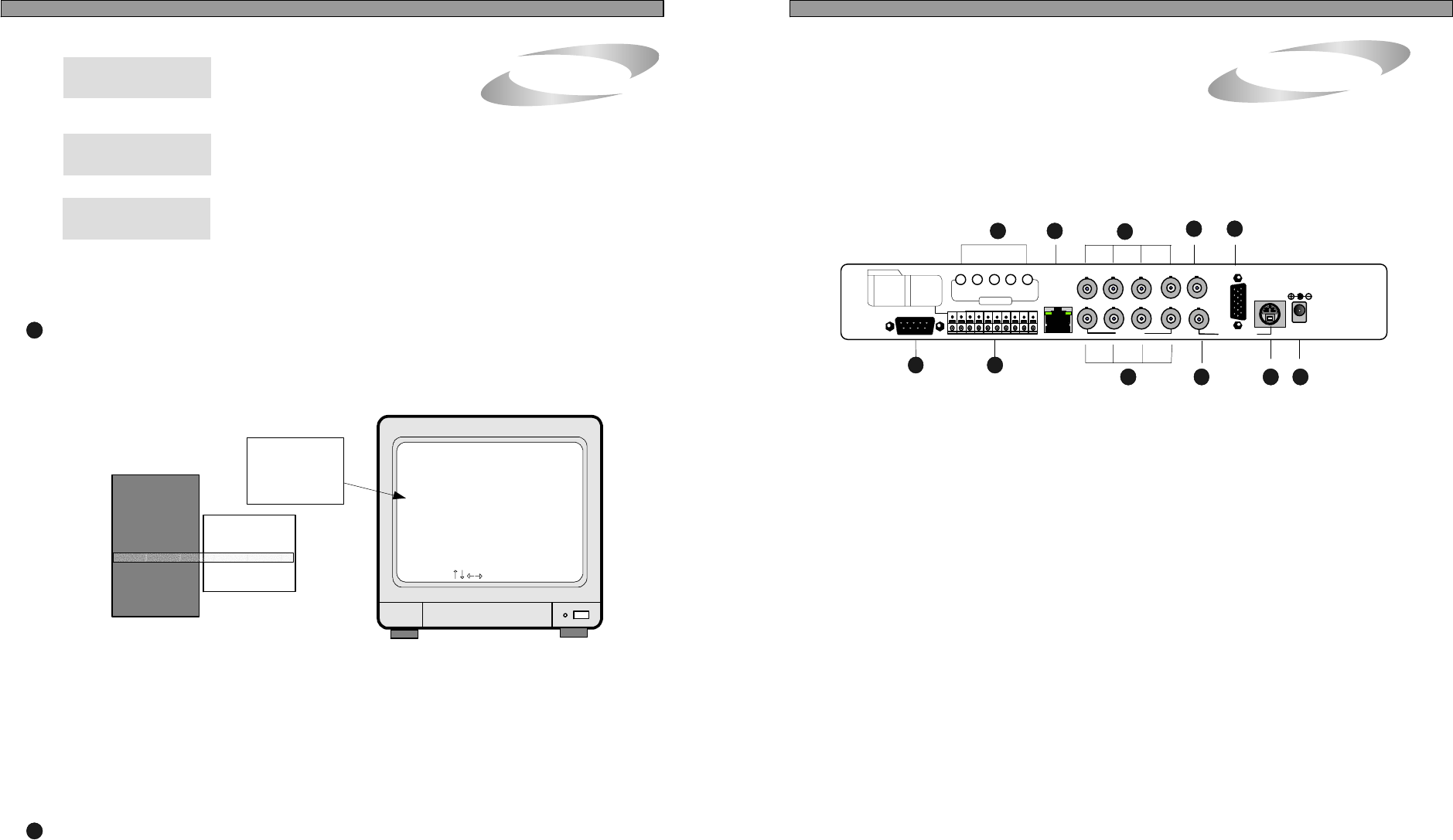
3.Unit Description
4
5. Camera Connection
6. LOOP Output
7. VCR Connection
8. MONITOR Connection
10. S-VHS Connection
3. AUDIO : 4 Input and 1 output
2. PAN/TILT Controller, Sensor Input/Output
1. RS-232C Port Connection
4. LAN (TCP/IP)
9. VGA Connection
11. D/C Power Connection
NOTICE : When connecting with other applications, be sure to turn off the system.
1
43
7
8
9
10 11
ALL ABOUT IMAGE RECOGNITION & PROCESSINGALL ABOUT IMAGE RECOGNITION & PROCESSING
2.
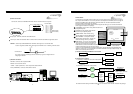
Rear Panel
Rear Panel
DC 12V
ETHERNET
RS-232C
6
5
VCRCH1 CH2 CH3 CH4
MONITOR
LOOP
CommPort
V
G
A
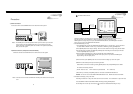
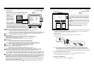
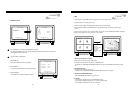
Procedure to control PTZ camera while you see live picture
1. Default PTZ camera : First select PTZ camera model connected to DVMR unit in the PANTILT COMMAND
SETUP menu. In live view mode, press [P/T] button and set CAM (Starts from 000) at camera ID which
is set on PTZ camera (DIP switch on PTZ camera) before you connect it to DVMR unit. Then select
command you want to execute using [LEFT] and [RIGHT] buttons. While you press [PLAY] button,
command you selected is executed.
2. USER DEFINE : In case you input protocols of PTZ camera which is not one of Default cameras, select
USER DEFINE in PANTILT COMMAND SETUP. Then press [P/T] button and set CAM (Ranges from
001 to 004) at any one from 001 to 004. CAM number must be the same as CH number which you set
when you input protocol of PTZ camera in USER DEFINE. Using [LEFT] and [RIGHT] button, select
command you want to execute and press [PLAY] button to execute selected command. While you press
[PLAY] button, command you selected is executed.
PAN/TILT COMMAND SETUP
AUDIO
SPK MIC4 MIC3 MIC2 MIC1
1 2 3 4 5 6 7 8 9 10
2
FUNCTION
6 ALARM GND
7 ALARM D4
8 ALARM D3
9 ALARM D2
10 ALARM D1
1 RS 485 D-
2 RS 485 D+
3 RELAY COM
4 RELAY NC
5 RELAY NO