


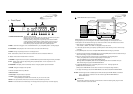
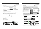
ETHERNET
RS-232C
AUDIO
FUNCTION
1 RS 485 D-
2 RS 485 D+
3 RELAY COM
4 RELAY NC
5 RELAY NO
6 ALARM GND
7 ALARM D4
8 ALARM D3
9 ALARM D2
10 ALARM D1
SPK MIC4 MIC3 MIC2 MIC1
1 2 3 4 5 6 7 8 9 10
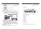
4. Installation
7
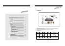
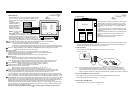
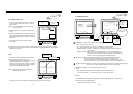
5) Sensor Connection
Connect the Sensor to the SENSOR INPUT/OUTPUT on the Rear Panel of the system
6) Network Connection
RS-232C : Connect to PC to operate DVMR
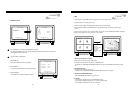
NOTICE : Sensor input is RECOGNIZED as LOW when alarm signal is on a level with GND,
and it is recognized as HIGH when alarm signal is FLOATING or 5V. Following is internal circuit.
Internal Circuit
D1
5
V
Thus, there is a danger of damage, when the sensor input goes to a Negative level or
voltage higher than 5V.
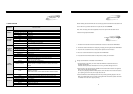
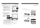
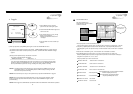
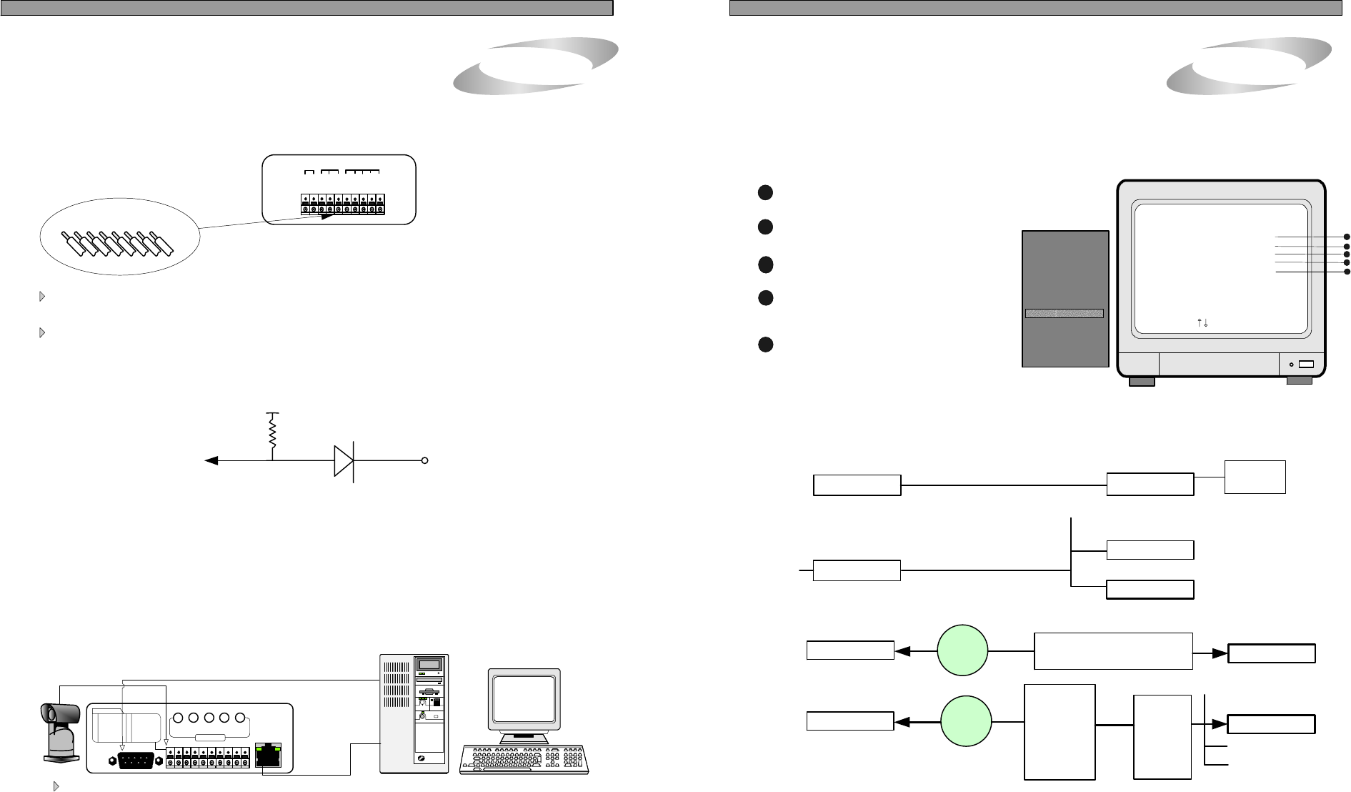
7. TCP/IP SETUP
5. Operation
24
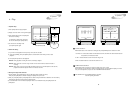
TCP/IP SETUP
IP ADDRESS
GATEWAY
SUBNET MASK
MAC ADDRESS
DHCP SETUP
SELECT , PRESS ENTER
1
2
3
4
4
3
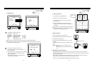
MAC ADDRESS : It is unique ID number
provided by the manufacturer, and the user
should not change under any condition.
TCP/IP option of this DVMR system enables user to see live pictures and recorded pictures via internet
line, far apart from DVMR unit. To see live pictures or recorded pictures of DVMR, users must assign IP
address into DVMR together with Gateway and Subnet mask first, and then install Remote Viewer
Program included in the package on client PC.
For detail procedure for installing Remote Viewer Program and setting up, refer to manual for Remote
Viewer program included in the package.
SUBNET MASK : Enter numbers using
direction buttons and press [MENU] button.
SYSTEM SETUP
DISPLAY SETUP
CAMERA TITLE
TIME/DATE SETUP
ALARM/MOTION SETUP
RECORD SETUP
TCP/IP SETUP
MISCELLANEOUS
FACTORY DEFAULT
ALL ABOUT IMAGE RECOGNITION & PROCESSINGALL ABOUT IMAGE RECOGNITION & PROCESSING
Terminal block
Pin 1 Alarm1
Pin 2 Alarm2
Pin 3 Alarm3
Pin 4 Alarm4
Pin 5 GND
Pin 6 NO( Normal Open )
Pin 7 NC( Normal Close)
Pin 8 COM
Relay output : COM+NC, COM+NO OR COM+NC+NO
Alarm input : Short-circuit between Alarm1, Alarm2, Alarm3 or Alarm4 and GND is recognized as alarm.
For more details, refer to arrangements RS-232c pins in page 32.
RS 485 : Connect to PTZ camera
RJ-45 (ETHERNET) : Connect to LAN, WAN or Internet
5
DHCP SETUP : In case you connect DVMR
unit to LAN network under router/Gateway/IP
sharer which has DHCP server function, set
DHCP SETUP at DHCP, and DVMR unit automatically gets
IP data automatically during the process of booting.
In case you connect DVMR unit to leased line with static IP, Router/Gateway connected ADSL(with
static IP or dynamic IP), you are requested to set DHCP at MANUAL and input IP data manually. For
details, refer to Remote Viewer manual.
5
TCP/IP SETUP
PTZ
CAMERA
G
N
D
D
4
D
3
D
2
C
O
M
N
C
N
O
D
1
ALARM
RELAY
D
--
D
+
IP ADDRESS : Enter numbers using direction buttons and
press [MENU] button.
GATEWAY : Enter numbers using direction
buttons and press [MENU] button.
1
2
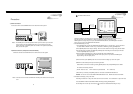
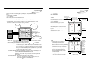
1) Concept of accessing to DVMR unit via IP network
PC
DVMR unit
PTZ
Camera
LAN, WAN, or Internet
Client program
(remote viewer)
TCP/IP setup
2) Conditions of IP network
a) Accessing to DVMR unit in the same Intranet(LAN)
DHCP server
Router/Gateway
IP Sharer
DVMR unit
PC
LAN
b) Accessing to DVMR unit via Internet line
InternetPC
Leased line : Manual
Cable modem : Automatic
Leased line w/ static IP
Cable modem w/ dynamic IP
DVMR unit
Client program
(remote viewer)
InternetPC
ADSL
modem
w/
dynamic IP
or
static IP
DVMR unit
Client program
(remote viewer)
Router
or
Gateway
PPPoE
protocol
Port Forwarding
(IP Forwarding)
Manual
For details of TCP/IP setting in DVMR unit and PC, refer to “Remote Viewer manual” included in the package.
DHCP SETUP
DHCP SETUP
DHCP SETUP
Automatic
Other devices
24
AUDIO : 1 audio input/channel, 1 audio output from selected channel.
COM NC NO GND D4 D3 D2 D1