


4
NAMES AND
FUNCTIONS
BASIC
OPERATIONS
ADVANCED
OPERATIONS
TROUBLESHOOTING
OTHERS
ENGLISH
NAMES AND
FUNCTIONS
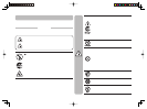
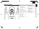
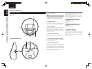
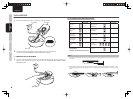
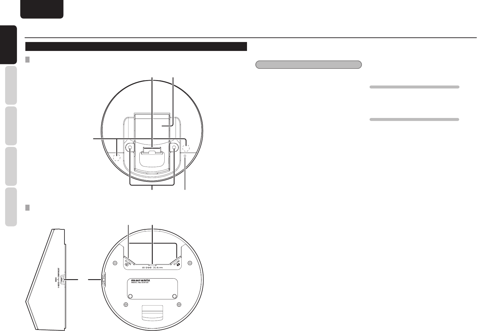
BASE UNIT (IS301DS)
TOP VIEW
d
g
f
a
s
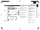
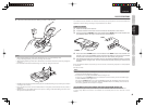
SIDE AND BOTTOM VIEWS
jk
h
NAMES AND FUNCTIONS
a Handset connector
Connect the handset here.
Note
NEVER connect an iPod directly with this
connector, because the shape of this connector is
different from the docking connector of the iPods.
s Handset holder
When the base unit is mounted on a wall, raise
this holder. For details, see INSTALLATION
PROCEDURES FOR THE BASE UNIT (page 13).
d Power indicator
This indicator lights when power is supplied from
the AC adaptor or when the base unit is connected
with the powered extender via the IS-LINK cable.
It fl ashes when an infrared signal from the remote
controller is received.
f Holes for wall mounting
Use these holes when mounting the base unit on
a wall.
g Infrared signal reception window
This is the reception window for infrared signals
from the remote controller.
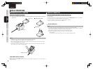
h Video selection switch
Select video signals (S-VIDEO/VIDEO/
COMPONENT) that are output from the extender.
If the Video selection switch is switched during
video playback, the output signal may not be
switched, depending on the type of iPods being
connected. In such a case, go back to the MENU
screen then restart video playback.
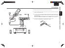
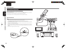
j IS-LINK A/V terminals
Used to connect the base unit and the extender via
the supplied IS-LINK cables.
Before connection, unplug the power cord then
check that the connections to the IS-LINK A and V
terminals are properly made.
TRANSMISSION SIGNALS VIA IS-LINK A
• Audio signal
• Remote control signal
• Power
TRANSMISSION SIGNALS VIA IS-LINK V
• Video signal
• External control signal
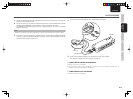
k AC adaptor terminal
Connect the supplied AC adaptor.
If the base unit and the extender is connected by
the IS-LINK A connection, power will be supplied
from the extender.
Therefore, it is not required to connect the AC
adaptor to the base unit.