


3 Quick Start
CAUTION: Never connect or disconnect parts of the system when the system is powered up
as this may cause serious damage.
CONNECTION – Connection and usage are straightforward. However, care needs to be
taken with the following:
• Ensuring parts have been correctly connected – both power & signal considerations.
• Checking that all switches and jumpers are set correctly.
• The input signal is compatible.
• Legal & safety requirements have been met.
• If you are using supplied cables & accessories, ensure they are correct for the model
of video monitor.
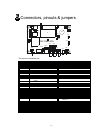
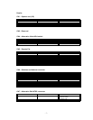
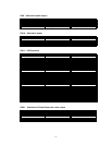
• If you are making your own cables & connectors refer carefully to the video monitor
specifications and the “Connectors, Pin outs & Jumpers” section in this user guide to
ensure the correct pin-to-pin wiring.
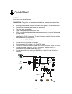
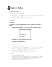
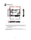
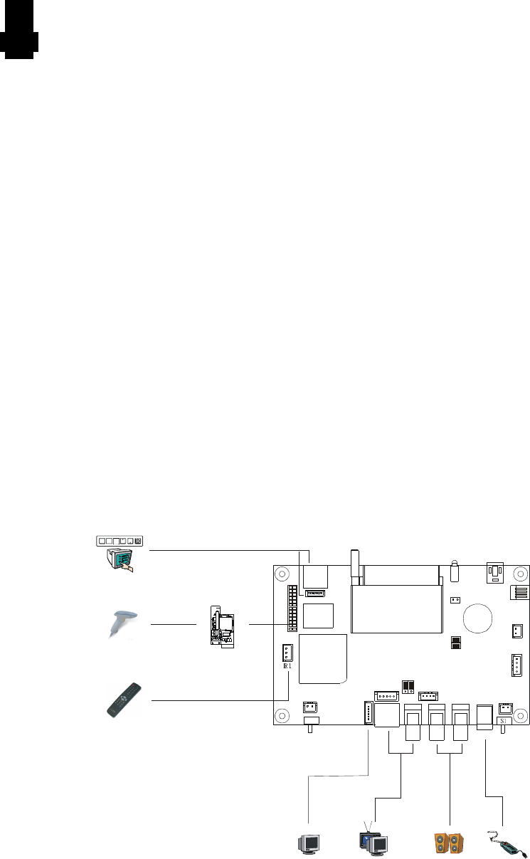
Basic connection for MV-FLASH M3+ :
• Connect the keys pad to CN5 (if required)
• Set correct switch (S1) settings. (e.g. PAL/NTSC switch)
• Connect the video and audio ext. cables from the MV-FLASH M3+ to the AV monitor.
• Connect the power supply (DC 12V @ 1.2A minimum. - ensure correct + & -
orientation) to the controller power input (PP1).
• Connect the on/off switch cable (p/n:4266804-01) or short Pin1-2 at S3 for “Auto
power on”
- 4 -
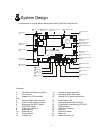
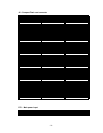
Power supply
Speaker
Monitor
Barcode reader
Touch screen/Keypad
C 6N
C 5N
J6
LED1
S3
C 7N
CN4
CNV1 CN9
PP1
J1
J2 J3 J4
BT1
MV-FLASH M3+
1
1
1
1
1
1
1
CN1
1
CN10
1
JA1
3
1
LED2
1
1
V 1R
CN11
1
RS-232 add on
board
VGA Monitor
Remote Control