


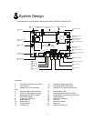
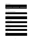
2 System Design
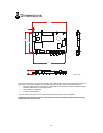
A typical setup of a Video Monitor display with a MV-FLASH M3+ looks like this:
C 6N
C 5N
J6
LED1
S3
C 7N
CNV1
CN9
PP1
J1
J2 J3 J4
BT1
MV-Flash M3+
1
1
1
1
1
1
1 SW and Button
Connector
4 Compact Flash card
connector
5 Power On/Off switch
6 Alternative PAL/NTSC
switch
7 PAL/NTSC switch
8 Power input (DC12V)
9 Audio [R] out
10 Audio [L] out
11 Composite out
12 S-Video out
14 Alternative
Video/VGA switch
15 Remote Ext.
16 Power/Status LED
CN1
1
CN10
1
JA1
3
1
LED2
1
1
V 1R
13 Alternative power
connector
3 Speaker out (L/R)
connector
17 Alternative power
LED connector
18 I/O expansion
connector
2 IR connector
CN11
1
CN4
1
CNV2
1
J5
JP
2
1
1
CN2
JP1
1
CNV3
1
19 USB connector
20 Alternative
Video out
21 VGA out
22 Video/VGA
switch
23 Reserved
24 Alternative Audio out
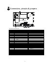
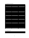
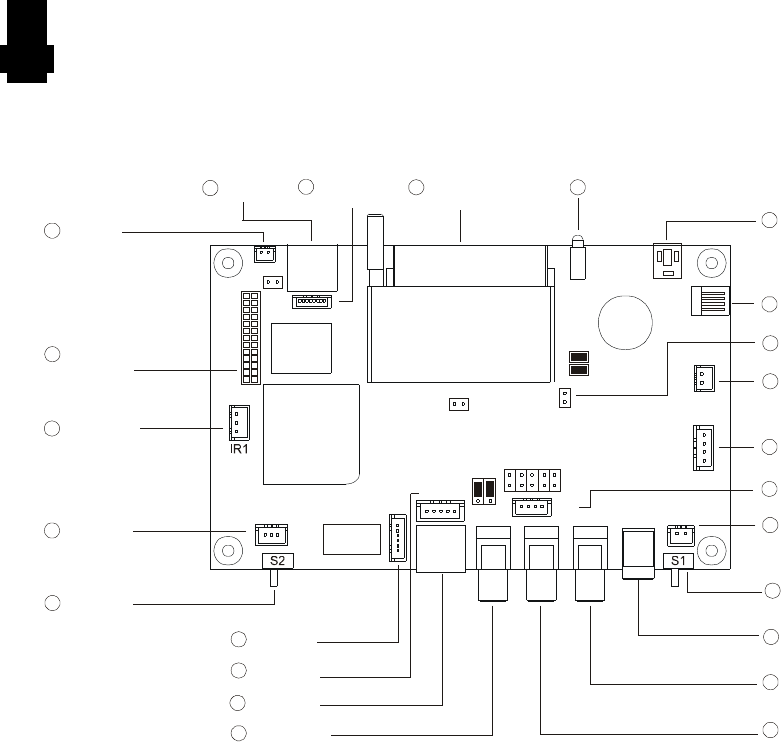
Summary:
1. Switches and Buttons connector 13. Alternative power connector
2. IR connector 14. Alternative Video/VGA switch
3. Speaker out (L/R) connector 15. Remote Ext. (8 buttons connection
only)
4. Compact Flash card connector 16. Power/Status LED
5. Power On/Off switch connector 17. Alternative power LED connector
6. Alternative PAL/NTSC switch 18. I/O expansion connector (eg. RS-232)
7. PAL/NTSC switch 19. USB connector
8. Power input (DC12V) 20. Alternative Video out
9. Audio right out 21. VGA out
10. Audio left out 22. Video/VGA switch
11. Composite out 23. Reserved
12. S-Video out 24. Alternative Audio out
- 2 -