


6
TK-860G/862G
INSTALLATION
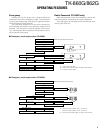
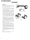
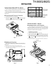
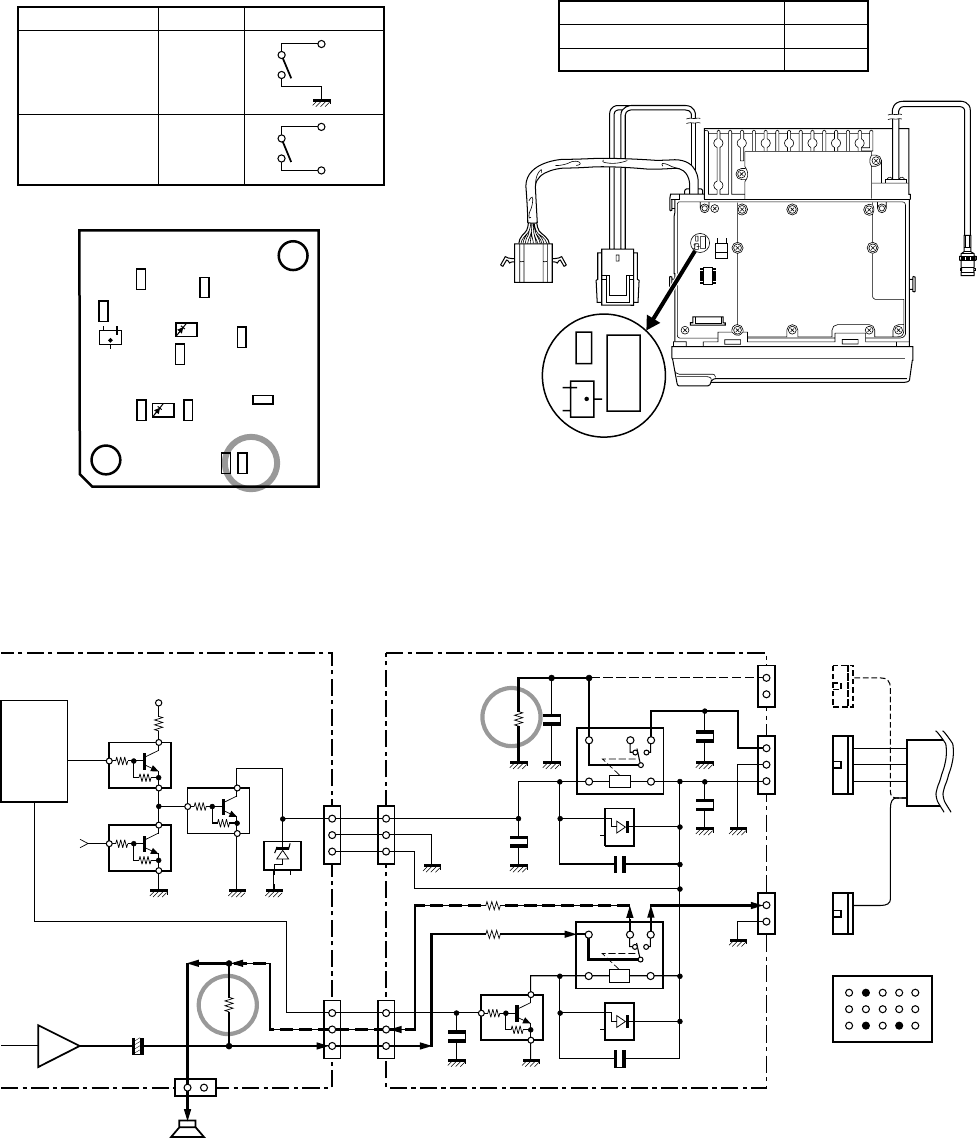
■ Others
If the PA and HR2 are not necessary and the speaker out-
put is output to an external unit through the KCT-19, connect
the KCT-19 C connector to CN8 on the TX-RX unit.
8C
R21
Q5
Q1
D2
Q6
Q1
Q6
4
IC9
Shift
register
IGN
±
+
±
+
KAP-1 (SWITCH UNIT : X41-3380-20)
W1
1
2
3
HOR
E
SB
W2
1
2
3
PA/LI
SPO
SPI
CN1
1
2
HR2
NC
CN2
1
2
3
HR1
E
SB
CN3
1
2
PAO/LIO
E
R1 0
C5 1000P
C6
1000P
C7
1000P
K2
D1
C3 0.01
C1
1000P
R3 0
R4 0
C2
1000P
D2
K1
C4 0.01
Q1
Q1 : DTD114EK
D1,2 : 1SS193
CN3
CN7
13
+
R153
Audio
power amp
IC13
CN8
1
2
SP
E
Internal/External
speaker
TX-RX UNIT
B
BRN
ORG
YEL
C
C
GRN
GRN
KCT-19
13 10 1
36
12
15
KCT-19 Terminal
6 : Earth
10 : HR1
12 : PA (HR2)
Fig. 6
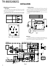
■ Modifying the Transceiver
• Horn alert
The signal from pin 4 of IC9 on the TX-RX unit turns Q5
and Q1 on and off and drives KAP-1 HA relay K2 to drive the
horn with a maximum of 2A.
The default output is HR1. The relay open output can be
obtained between HR1 and HR2 by removing R1 in the KAP-
1.
R1 Output form
HR1 (Default) Enable
HR2 Disable
HR1
HR1
HR2
R1
TX-RX UNIT
(A/2)
ANT
KCT-19
CN2
Q19
R122
R153
Fig. 4 KAP-1 foil side view
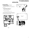
• Public address
The signal from pin 13 of IC9 on the TX-RX unit drives PA
relay K1 in the KAP-1 and switches the audio power ampli-
fier output between the external PA system (through KCT-
19) and internal and external speakers.
To use the PA function, R153 on the TX-RX unit must be
removed.
R153
Use the PA function Disable
Do not use the PA function Enable
Fig. 5