


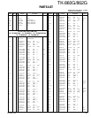
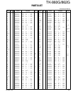
5
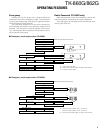
TK-860G/862G
INSTALLATION
2
3
4
1
3
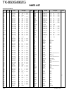
W1
W2
CN1
CN2
KCT-19
Cushion
(G13-1710-04)
CN3
CN7
1
CN3
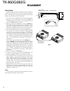
Fig. 3
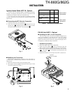
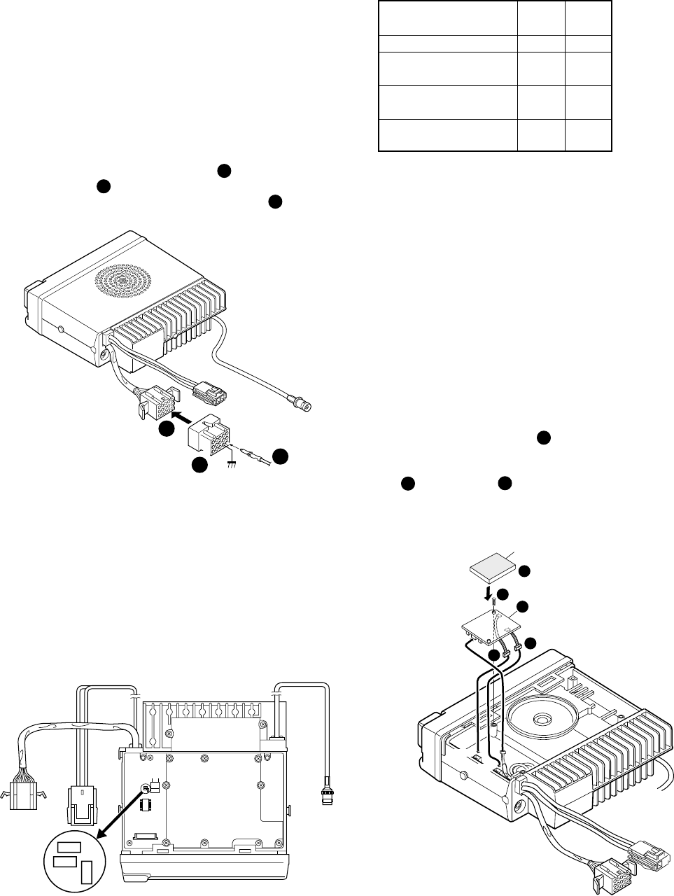
PA/HA Unit (KAP-1 : Option)
■ Installing the KAP-1 in the Transceiver
The Horn Alert (max. 2A drive) and Public Address func-
tions are enabled by inserting the KAP-1 W1 (3P; white/
black/red) into CN3 on the TX-RX unit, inserting W2 (3P;
green) into CN7 on the TX-RX unit, and connecting the KCT-
19 (option) to CN2 and CN3 of the KAP-1.
• Installation procedure
1. Open the upper case of the transceiver.
2. Insert the two cables ( ) with connectors from the
KAP-1 switch unit into the connectors on the transceiver.
3. Secure the switch unit board to the chassis with a screw
( ). The notch ( ) in the board must be placed at the
front left side.
4. Attach the cushion on the top of the KAP-1 switch unit.
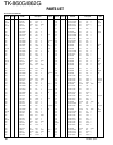
1
3
2
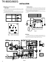
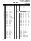
Ignition Sense Cable (KCT-18 : Option)
The KCT-18 is an optional cable for enabling the ignition
function. The ignition function lets you turn the power to the
transceiver on and off with the car ignition key.
If you use the Horn Alert function or the Manual Relay
function, you can turn the function off while driving with the
ignition key.
■ Connecting the KCT-18 to the Transceiver
1. Install the KCT-19 in the transceiver.
2. Insert the KCT-18 lead terminal ( ) into pin 3 of the
square plug ( ) supplied with the KCT-19, then insert
the square plug into the KCT-19 connector ( ).
2
1
3
1
3
6
13
15
KCT-18
KCT-19
Contact
1
2
3
Fig. 1
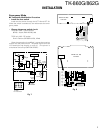
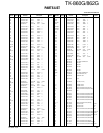
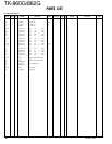
■ Modifying the Transceiver
Modify the transceiver as follows to turn the power or
the Horn Alert or Manual Relay function on and off with the
ignition key.
1. Remove the lower half of the transceiver case.
2. Set jumper resistors (0Ω) R134 and R135 of the TX-RX
unit (A/2) as shown in Table 1.
TX-RX UNIT
(A/2)
ANT
KCT-19
CN2
R134
R133
R135
Fig. 2
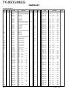
Operation when KCT-18 R134 R135
is connected
Enable Enable ← KCT-18 cannot
Power on/off and Horn Disable Enable be connected
Alert or AUX-A on/off
Horn Alert or AUX-A Enable Disable
on/off
Disable Disable ← Power cannot
be turned on
Table 1 R134 and R135 setup chart