17
TK- 860G/862G
ADJUSTMENT
Test Mode (TK-860G Only)
■ Test Mode Operating Features
This transceiver has a test mode.
To enter test mode,
press [SCN] key and turn power on. Hold [SCN] key un-
til test channel No. and test signalling No. appears on
LCD.
Test mode can be inhibited by programming. To exit
test mode, switch the power on again. The following func-
tions are available in test mode.
• Controls
[PTT] Used when making a transmission.
[MON] Monitor on and off.
[SCN] Sets to the tuning mode.
[A] Function on.
[D/A] RF power high and low.
[
] Changes signalling.
[
] Changes wide and narrow
[CH
/ ] Changes channel.
[Volume
/ ] Volume up/down.
• LCD indicator
"SCN" Unused.
"AUX" Lights at RF power low.
"MON" Lights at monitor on.
"Right side dot" Lights at narrow.
• LED indicator
Red LED Lights during transmission.
Green LED Lights when there is a carrier.
■ Frequency and Signalling
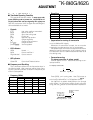
The set has been adjusted for the frequencies shown in
the following table. When required, re-adjust them follow-
ing the adjustment procedure to obtain the frequencies you
want in actual operation.
• Frequency (MHz)
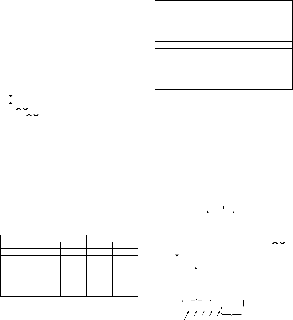
Channel No. TK-860G/862G (K2) Tk-860G (M2)
RX TX RX TX
1 (Center) 498.55000 498.60000 502.55000 502.60000
2 (Low) 485.05000 485.10000 485.05000 485.10000
3 (High) 511.95000 511.90000 519.95000 519.90000
4 498.50000 498.50000 502.00000 502.00000
5 498.70000 498.70000 502.20000 502.20000
6 498.90000 498.90000 502.40000 502.40000
7~16 – – – –
• Signalling
Signalling No. RX TX
1 None None
2 None 100Hz square
3 QT 67.0Hz QT 67.0Hz
4 QT 151.4Hz QT 151.4Hz
5 QT 210.7Hz QT 210.7Hz
6 QT 250.3Hz QT 250.3Hz
7 DQT D023N DQT D023N
8 DQT D754I DQT D754I
9 DTMF DEC, (159D) DTMF ENC, (159D)
10 None DTMF tone (9)
11 2-tone 321.7/928.1Hz 2-tone 321.7/928.1Hz
12 Single tone 1200Hz Single tone 1200Hz
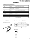
• Preparations for tuning the transceiver
Before attempting to tune the transceiver, connect the
unit to a suitable power supply.
Whenever the transmitter is turned, the unit must be
connected to a suitable dummy load (i.e. power meter).
The speaker output connector must be terminated with a
4Ω dummy load and connected to an AC voltmeter and an
audio distortion meter or a SINAD measurement meter at all
times during tuning.
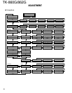
• Transceiver tuning
(To place transceiver in tuning mode)
Channel appears on LCD. Set channel according to tun-
ing requirements.
LCD display (Test mode)
11
–
Channel No. Signalling No.
Press [SCN], now in tuning mode. Use [D/A] button to
write tuning data through tuning modes, and [CH
/ ] to
adjust tuning requirements (1 to 256 appears on LCD).
Use [
] button to select the adjustment item through
tuning modes. Use [A] button to adjust 3-point or 5-point
tuning, and use [
] button to switch between wide/narrow.
LCD display (Tuning mode)
F
RE
Q
1
Adjustment
(1~256)
Adjustment item
..... .
Point tuning indicator
Wide/Narrow indicator
Off : Wide
On : Narrow


