


4
English
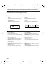
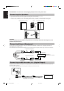
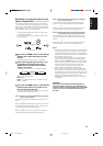
OPTICAL
DIGITAL OUT
Cap
MD recorder, etc. (not supplied)
To optical digital
input
Optical digital cord (not supplied)
Signal cord (not supplied)
Signal cord (not supplied)
Pin-plug x 2
Pin-plug x 2Pin-plug x 2
Pin-plug x 2
To audio output
To audio input
MD recorder or
cassette deck (not supplied)
LINE OUT
LINE IN
(AUX)
RL
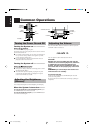
CAUTION: Make all connections before plugging the System into an AC power outlet.
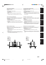
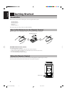
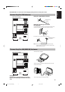
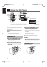
Connecting the Speakers
For each speaker, connect one end of the speaker wire to the speaker terminals on the back of the System.
1. Open each of the terminals and insert the speaker wires firmly, then close the terminals.
2. Connect the red (+) and black (–) wires of the right side speaker to the red (+) and black (–) terminals marked R on the System.
Connect the red (+) and black (–) wires of the left side speaker to the red (+) and black (–) terminals marked L on the System.
CAUTION:
If a TV is installed near the speakers, the picture on the TV may be distorted. If this happens, set the
speakers away from the TV.
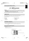
Connecting External Equipment
Connect signal cords (not supplied) between the System’s LINE IN (AUX)/LINE OUT terminals and the output/input terminals of an
external MD recorder, cassette deck, etc.
You can then listen to the external source through the System, or record the System’s CD player, cassette tape, or tuner to the external unit.
Connecting an MD Recorder, etc. (Digital Output)
Unplug the cap and connect an optical digital cord (not supplied) between the System’s OPTICAL DIGITAL OUT terminal and the input
terminal of an MD recorder, etc.
You can record the digital output signal from the System’s CD Player to the MD recorder, etc.
Right speaker (rear side)
Left speaker (rear side)
L
R
SPEAKERS
IMPEDANCE
MIN 4Ω
Black
EN01-11.UX-V30R/V330R[E] 00.1.20, 5:41 PM4