


Filename [MV5S_05Name.fm]
Masterpage:Left+
18 EN
GET OVER IT! – CONNECTION –
Page 18 Monday, 28 February 2005 16:43
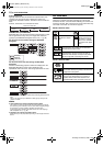
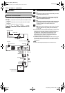
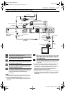
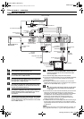
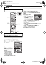
Component Video Connection
1 Disconnect the antenna from the TV.
2 Connect the antenna to the antenna input connector
on the cable box or DBS receiver.
3 Connect the RF cable between the unit’s [VHF/UHF
IN] connector to the antenna output connector on
the cable box or DBS receiver.
4 Connect the supplied RF cable between the [VHF/
UHF OUT] connector on the rear panel of the unit
and the TV’s antenna terminal.
5 Connect the supplied audio/video cable between the
[VIDEO/AUDIO OUTPUT (DVD/VCR)] connectors
on the unit and the TV’s audio/video input
connectors.
6 Connect the audio/video cable between the [VIDEO/
AUDIO INPUT (DVD/VCR)] connectors on the unit
and the audio/video output connectors on the cable
box or DBS receiver.
7 Connect the unit’s [COMPONENT VIDEO OUT (Y/
PB/PR)] connectors to the TV’s component video
input connectors.
● You can obtain high-quality component video pictures.
● If your TV is not stereo-capable, use the unit’s [AUDIO OUTPUT]
connectors to connect to an audio amplifier for Hi-Fi stereo
sound reproduction.
● By using the component video connection, you can view the
images in the progressive mode. For switching to the progressive
mode, refer to “Scan Mode Set” (੬ pg. 74).
8 Plug the end of the AC power cord into an AC outlet.
This unit performs Plug & Play Set automatically.
(
੬ pg. 19)
● The clock and tuner channels will automatically be set when the
antenna is connected and when the AC power cord is first
connected to an AC outlet. (If “AUTO” and the channel indicator
are displayed on the front display panel before the unit is
powered on, the clock and tuner channels are being set
automatically. Wait for the time to be displayed on the front
display panel before turning on the unit.)
● “LOADING” blinks on the front display panel when the AC plug of
the AC power cord is connected into an AC outlet and it takes
approximately 50 seconds for the unit to be turned on. This is not
a malfunction.
NOTE:
When watching the images on the VHS deck with this connection, set
to the progressive scan mode. (
੬ pg. 58, “VHS Progressive Scan”)
Antenna or Cable
Matching transformer
(not supplied)
Coaxial cable
AC outlet
Back of cable box or
DBS receiver
Component video cable
(not supplied)
Flat feeder
AC power cord
To 75 ohm terminal
Audio/video cable
(supplied)
RF cable (not supplied)
To [VIDEO/AUDIO INPUT
(DVD/VCR)]
RF cable
(not supplied)
To audio/video input
connectors
To component video
input connector
To antenna input
connector
To
[COMPONENT
VIDEO OUT (Y/
P
B
/P
R
)]
To antenna output
connector
To [VIDEO/
AUDIO OUTPUT
(DVD/VCR)]
Audio/video
cable
(not supplied)
To audio/video
output connectors
TV
Back of unit
To [VHF/UHF
OUT]
To [VHF/UHF IN]
RF cable
(supplied)
MV5S_00.book Page 18 Monday, February 28, 2005 6:07 PM