


Filename [MV5S_05Name.fm]
Masterpage:Left0
12 EN
Page 12 Monday, 28 February 2005 18:11
INDEX
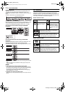
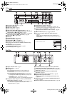
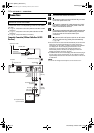
Front View
A Eject Button (x (EJECT)) ੬ pg. 27
B Cassette Loading Slot
C VHS Lamp (VHS)
੬ pg. 27
D DVD Lamp (DVD)
੬ pg. 26
E Open/Close Button (x (OPEN/CLOSE))
੬ pg. 11
F Reverse Search Button (3) (DVD deck)
੬ pg. 45, 52
Rewind Button (3) (VHS deck)
੬ pg. 57
G Forward Search Button (5) (DVD deck)
੬ pg. 45, 52
Fast Forward Button (5) (VHS deck)
੬ pg. 57
H Stop Button (8)
੬ pg. 26, 27
I Disc Tray
J Play Button (4)
੬ pg. 26, 27
K Pause Button (9)
੬ pg. 26, 57
L Record Button (7)
੬ pg. 28, 30
M Standby/On Button (STANDBY/ON 1)
N S-video Input Connector (S-VIDEO) (DVD deck only)
੬ pg. 42
O Video/Audio Input Connectors
(VIDEO/AUDIO ((MONO) L/R))
੬ pg. 42
P Front Display Panel
੬ pg. 13
Q Infrared Beam Receiving Window
R VHS/DVD Select Button* (VHS/DVD)
੬ pg. 26, 27
* This button will not function during navigation mode or set up mode.
S Dubbing Button (DUBBING) ੬ pg.38–40
Dubbing Direction Buttons (VHS]/}DVD)
੬ pg. 37 –
40
T Channel Buttons (CH +/–)
੬ pg. 28, 30, 41
U DV Input connector (DV IN (i*)) (DVD deck only)
੬ pg. 41
* i (i.Link) refers to the IEEE1394-1995 industry specification and
extensions thereof. The i logo is used for products compliant with the
i.Link standard.
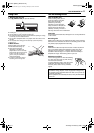
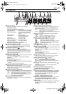
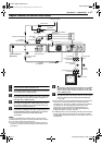
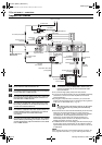
Rear View
A Region Number Label ੬ pg. 9
B AC Power Cord
੬ pg. 16
C Cooling Fan
● This prevents the temperature from rising inside the unit.
Do not remove it.
● Install the unit so as not to block the area around the fan.
● The cooling fan on the rear of the unit may be activated even if
the unit is turned off in the following cases;
— In the Automatic Satellite Program Recording standby mode
(
੬ pg. 36)
— when “AUTO CLOCK ” is set to “ON” (
੬ pg. 21)
(Set “AUTO CLOCK ” to “OFF” if you mind the noise of the fan.)
D Component Video Output Connectors (COMPONENT
VIDEO OUT (Y/P
B/PR)) ੬ pg. 16
● This component video output enables you to watch the images on
the VHS deck in Progressive scan mode, refer to “VHS
Progressive Scan” (
੬ pg. 58).
E S-video/Video/Audio Output Connectors (S VIDEO/
VIDEO/AUDIO OUTPUT) (DVD deck only)
੬ pg. 16
F S-video Input Connector (S VIDEO INPUT (L-1)) (DVD
deck only)
੬ pg. 43
G Video/Audio Output Connectors (VIDEO/AUDIO
OUTPUT)
੬ pg. 43
H Antenna Input Connector (VHF/UHF IN)
੬ pg. 16
I Digital Audio Output Connectors
(DIGITAL AUDIO OUT (COAXIAL)) (DVD deck only)
੬ pg. 44, 71
J Video/Audio Input Connectors (VIDEO/AUDIO INPUT
(L-1))
੬ pg. 43
K Antenna Output Connector (VHF/UHF OUT)
੬ pg. 16
VHS/DVD
DVDVHS
REC
VHS DVDDUBBING
CH
DV IN
STANDBY/ON
S-VIDEO VIDEO AUDIO
M
C
D
FEGHIJ
K LBA
NPQRSUO
T
To access covered connectors, push and
open the connector cover.
STAN DB Y / ON
S-VIDEO VIDEO AUDIO
PUSH-OPEN
OUTPUT
OUTPUT
VHF/UHF
INPUT L-1
DVD
DVD DVD
DVD /
VCR
DVD /
VCR
IN
L
R
DIGITAL
AUDIO OUT
COMPONENT
VIDEO OUT
VIDEO
S VIDEO S VIDEO
AUDIO
L
R
VIDEO
AUDIO
L
R
VIDEO
AUDIO
PCM/
STREAM
OUT
COAXIAL
Y
P
P
B
R
AEFCDB
G
H
JKI
MV5S_00.book Page 12 Monday, February 28, 2005 6:13 PM