


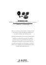
4 JL AUDIO ZR650-CSi
GETTING STARTED:
• Turn off the audio system. It is also advisable
to disconnect the negative (–) terminal of your
vehicle’s battery whenever performing
installation work.
• Before cutting, drilling or inserting any screw, check
clearances on both sides of the planned mounting
surface. Also check for any potential obstacles, such
as window tracks and motors, wiring harnesses, etc.
Check both sides of the vehicle, many vehicles are
not symmetrical!
• Always wear protective eyewear.
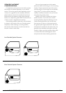
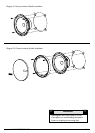
CROSSOVER NETWORK INSTALLATION:
The crossover networks supplied with your ZR
System should be installed in a dry location inside
your vehicle. DO NOT INSTALL THEM INSIDE OF
A DOOR! Doors often get wet on the inside, which
can damage your crossover networks and could
potentially damage your entire sound system. The
crossovers can be screwed into a solid surface via
two holes located under the protective cover of the
case. To access these holes, simply squeeze the sides
of the cover while gently pulling the cover away from
the base. Make sure that your mounting location will
not cause damage to wiring, fuel lines, brake lines or
any other vital component of your vehicle. Once you
have screwed the case in and made your connections,
snap the protective cover back into place.
!!
WARNING
!!
It is absolutely vital that your component system is
connected as shown in this manual. Failure to connect
the system as shown may result in damage to your
speakers which is NOT covered under warranty.
Do not substitute different crossover networks into
your ZR System. Do not use crossover networks
intended for different ZR models.
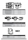
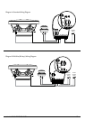
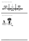
WIRING DIAGRAMS - STANDARD AND
BI-AMP / BI-WIRE METHODS:
The input to the crossover networks can be set
up in one of the following two ways:
Standard: This wiring configuration is used when
you wish to drive each crossover with a single
amplifier channel or pair of wires. In this mode, you
will only use the input connections marked “INL+”
and “INL–”on the crossover circuit board (“INH+”
and “INH–” are not used). Your crossovers are pre-
set in this mode at the factory. This mode is selected
by placing the pair of jumper bars shown in Diagram
A to the lower position marked "STD”. Tweeter
(“T+” and “T–”) and woofer output connections
(“W+” and “W–”)are made as shown in Diagram A.
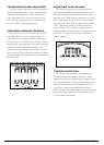
Bi-Wire (Bi-Amp): This position is selected by
placing the input mode selection jumper bars in the
upper position as shown in Diagram B. In this mode,
the inputs to the woofer’s low-pass filter and the
tweeter’s high-pass filter are electrically isolated. This
permits connection of different amplifier channels to
the woofer and tweeter sections (bi-amp), or separate
wire pairs for each section from a single amplifier
channel (bi-wire). In this mode, you will use the Input
connections marked “INL+” and “INL–” to drive the
low-pass woofer section of the crossover and “INH+”
and “INH–” to drive the high-pass tweeter section of
the crossover. Tweeter (“T+” and “T–”) and woofer
output connections (“W+” and “W–”)are made as
shown in Diagram B.
Please note that the use of additional active
filtering for the woofer low-pass or tweeter high-
pass is not necessary or recommended in this
mode. The crossover network has been engineered
to shape the system response... additional filters
may degrade performance.