


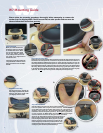


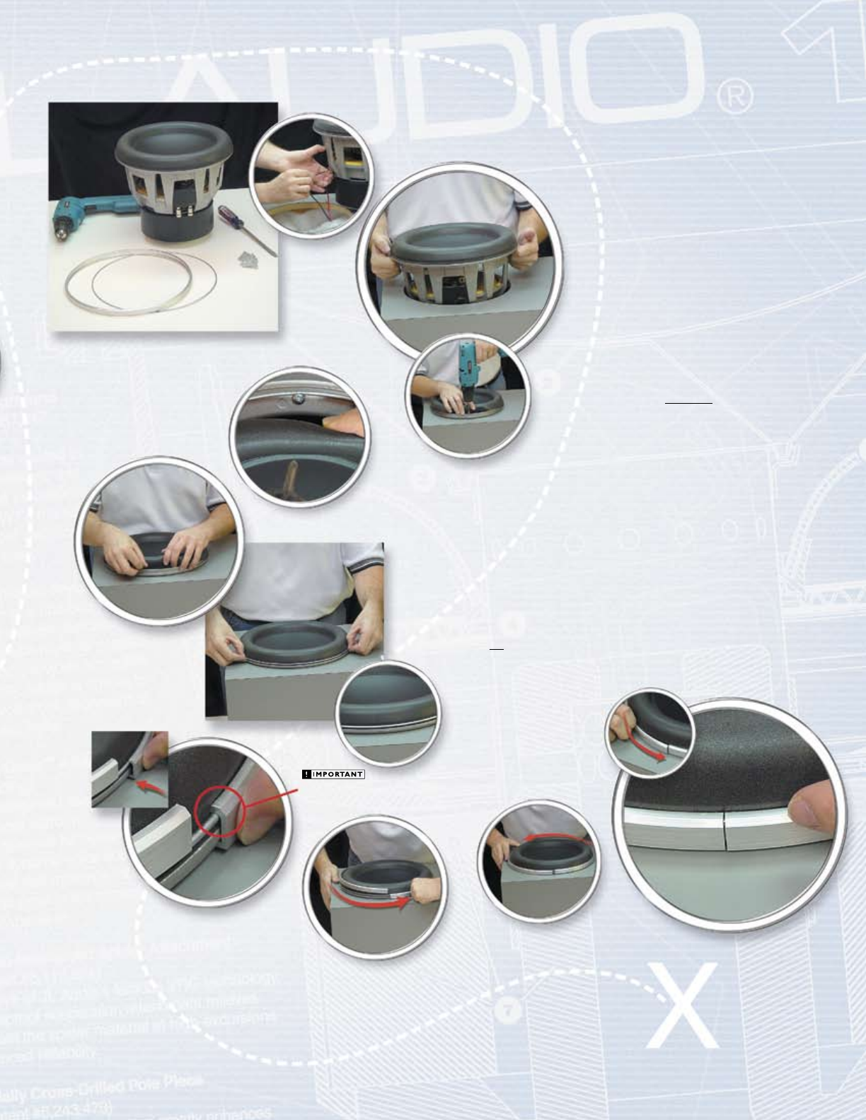
Step 6: Connect the speaker wires and
place the W7 into the enclosure
Connect the positive wire to the red terminal and the negative wire to
the black terminal of the W7 (picture 6a). The 13W7 (not shown) has dual
voice coils and must be wired with its coils in series or in parallel. Once
the speaker is wired, gently lower it into the enclosure (picture 6b). This is
difficult on a vertical mounting surface (because of the speaker’s
weight) so you should enlist the help of a second person. If you
need a better grip (or are afraid of smashing your fingers)
you can grasp the inside of the speaker’s mounting flange
(remember, the surround moves out of the way). This tip
is particularly useful with the 13W7.
Step 5: Ready to Install
You are now ready to install the
W7 into its enclosure. The parts are
shown below.
Step 7: Screw it in (12 times)
Line up the screw holes of the frame
with the holes that you have pre-
drilled in your enclosure (you did
pre-drill the holes, right?). The W7
should be attached with heavy
screws such as the ones supplied with
the speaker. This will necessitate pre-
drilling. The use of inferior hardware
(i.e. drywall screws) may lead to
disastrous consequences, so don’t
do it. While holding the surround
back with two fingers (picture 7a),
screw the speaker into the enclosure
(picture 7b). Once all twelve screws
are in place (you did use all twelve,
right?), place the surround back over
the outside of the speaker frame
(picture 7c).
Step 8: Attach O-Ring
Next, take the steel O-Ring that you
removed in step 3, and place it over
the outside of the surround. Push it
down evenly (do not seat one side
first) to make sure it seats the lower
lip of the surround down to the
frame (pictures 8a, 8b).
“click”
Step 9: Attach Clamp-Ring
Place the seam of the clamp-ring where it will be
least visible in the installation (usually at the bottom
of the speaker). Start one end of the clamp-ring by pressing i t
in firmly (pictures 9a, 9b). Then work your way around from that point
around the speaker, pushing the clamp-ring inward and in the direction
of the circumference of the frame (pictures 9c, 9d). If you have achieved a
tight fit all around, the seam will be small when you reach the starting point
again (pictures 9e, 9f). Check the entire circumference for a tight fit just
to be sure.
That’s it!
You’ve just installed a W7!
5
6a
6b
7a
7b
7c
8a
8b
9a
9b
9c
9d
9f
9e
Be sure that the beveled edge of
the clamp-ring is “pointing” towards the front of the
speaker. The clamp-ring is only designed to work in
this orientation.
5