


17
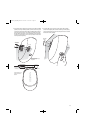
STAND-MOUNTING
IMPORTANT SAFETY NOTE:
CAUTION
The supplied floor stand adapters facilitate installation with a variety of general-
purpose floor stands available from many manufacturers. Since different stands
will have different weight capacities and stability characteristics, it is the
customer’s responsibility to check with the stand manufacturer or dealer to
ascertain whether that specific stand is capable of handling the weight and
proportions of these loudspeakers in a safe and stable manner. JBL, Inc.,
disclaims any liability for the selection of suitable floor stands and/or correct
compatibility between the selected stand and the supplied stand adapter.
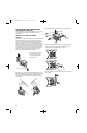
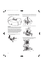
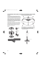
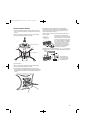
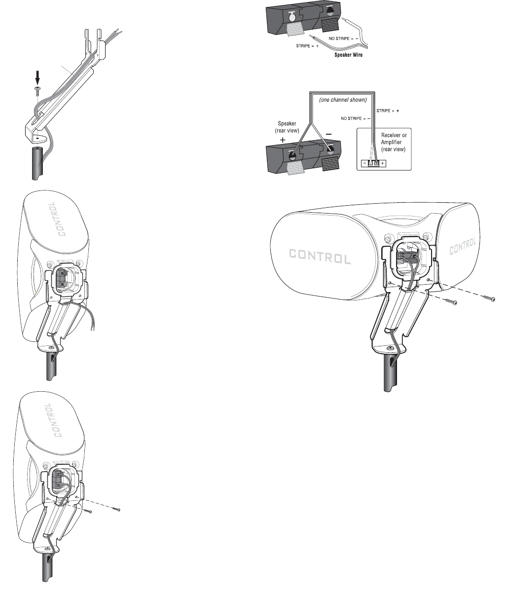
1. Attach the stand-mounting bracket
to the stand with the #1/4-20 x 1"
screw as shown.
2. Run the wiring as shown.
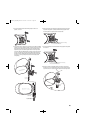
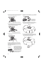
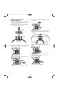
3. Place the JBL Control NOW speaker
on the stand-mount bracket and
stand, as shown.
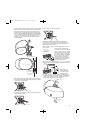
4. Use two #8-32 x 1/2" screws provided
to secure the JBL Control NOW
speaker to the stand.
5. Attach wires.
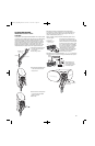
IMPORTANT: Make sure all equipment is turned off before making
any connections. For speaker connections, use a high-quality speaker wire
with polarity coding. The side of the wire with a ridge or other coding is
usually considered positive polarity (i.e., +).
NOTE: If desired, consult your local JBL dealer about speaker wire and
connection options.
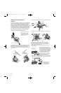
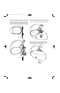
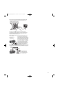
The speakers have coded terminals that
accept a variety of wire connectors. The most
common connection is shown in the diagram
to the left. To ensure proper polarity, connect
each + terminal on the back of the amplifier
or receiver to the respective + (red) terminal
on each speaker, as shown. Connect the
– (black) terminals in a similar way. See
the owner’s guides that were included with
your amplifier, receiver and television to
confirm connection procedures.
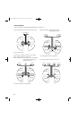
IMPORTANT: Do not reverse polarities (i.e., + to – or – to +) when making
connections. Doing so will cause poor imaging and diminished bass response.
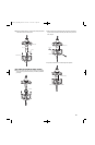
Wiring diagram shows
polarity connections for
one channel of a stereo or
home theater system.
An alternate orientation
shown here.
RED = +
BLACK = —
Standard
Connection
RED = +
BLACK = —
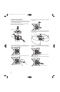
1. Strip 1/4" of wire
2. Press and push connector
3. Insert bare end;
release push connector
Stand
Stand-Mount Bracket
#1/4-20 x 1"
Screw Provided
Note trough in Stand-Mount
Bracket for
cable management.
#8-32 x 1/2" Screws
JBLP2605_CN_CNAW_PM-OM 4/23/08 12:57 PM Page 17