


4 VSW I AAP • Installation and Operation
Configuration
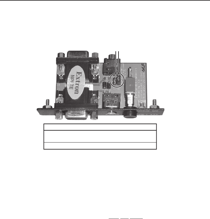
Setting VSW I AAP Jumpers
A jumper (figure 5) on the VSW I AAP may need to be shifted, from
jumper J6 (the default position) to J5, depending on the switcher to
which the VSW is connected. Refer to the applicable switcher’s manual
to see how to determine the switcher’s board version or level.
J5
J6
Jumper installed
J6
J5
Switcher compatibility
VSW 2VGA A, board revision C
SW VGArs, board part #20-1118-0x
VSW 2VGA A, board revision A
Figure 5 — VSW I AAP jumper positions
• If you are daisy chaining with a VSW 2VGA A that has a circuit board
that is revision C or higher, install the jumper on J6.
• If you are daisy chaining with a VSW 2VGA A that has a circuit board
that is revision A, install the jumper on J5.
• If you are daisy chaining with a SW VGArs that has a circuit board
whose part number is 20-1118-0x, install the jumper on J6.
N
The show me feature will not work when connected to
SW VGArs series switchers with a circuit board part number of
20-527-0x or 20-935-0x.