


1 VSW I AAP • Installation and Operation
Installation and Operation
VSW I AAP Interface
The VSW I AAP passive interface features a computer video input and
pass-through, an unbalanced stereo input and pass-through, and an
input select (Show Me) button. All VGA, audio, and control signals are
carried from the rear panel of the AAP to the switcher via a single Extron
VGA/audio cable assembly.
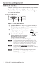
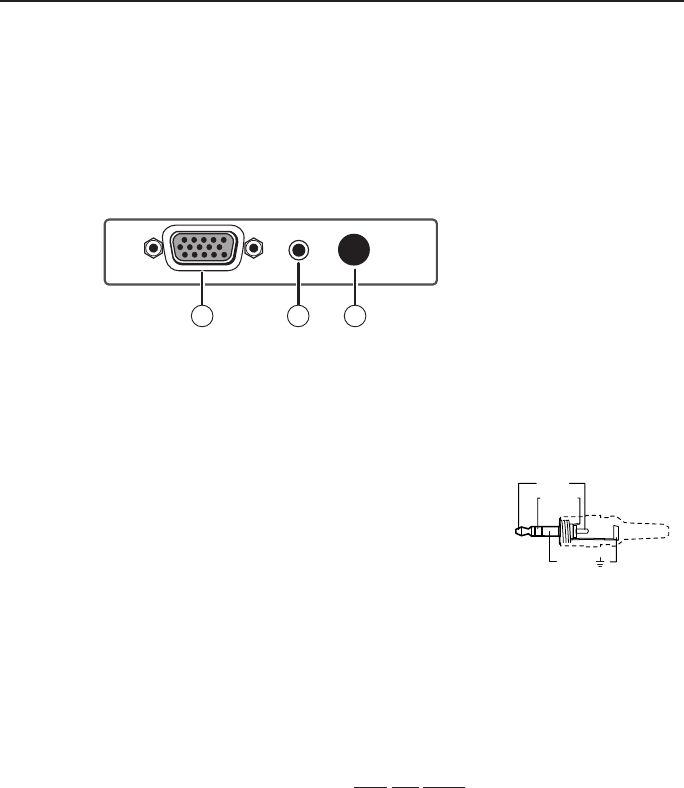
Front panel features
VSW I AAP
COMPUTER
AUDIO
SHOW ME
1 32
Figure 1 — Front panel features
a
Computer video input — Input VGA-UXGA, RGBHV, RGBS,
RGsB, RsGsBs, component video, or HDTV component video
through this 15-pin female VGA connector.
b
Audio input — Input unbalanced stereo
audio through this 3.5 mm mini audio
jack. See the diagram at right.
c
Input select (Show Me) button —
Pressing this button tells the connected
and compatible switcher to select this
AAP as the switcher's active input.
See "Rear panel features" on the following page.
N
The connected switcher must be compatible with this VGA
pin 5 pull-up control feature. The Extron VSW 2VGA A and
SW VGArs series switchers are compatible with this feature.
Check the user's manuals for these switchers for more detail.
N
The show me feature will not work when connected to
SW VGArs series switchers with a circuit board part number of
20-527-0x or 20-935-0x.
N
Use of the show me feature with specific switchers requires
that jumpers be set in the VSW I AAP. See “Setting
VSW I AAP Jumpers” on page 4.
Sleeve ( )
Ring (R)
Tip (L)
3.5 mm Stereo Plug Connector
(unbalanced)