


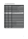
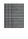
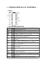
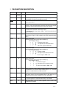
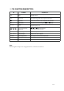

PIN FUNCTION DESCRIPTION
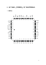
Pin Name Pin # Type Description
PD<7 -0> 11-16
18-19
I Multiplexed Cb, Y, and Cr digital video input bus.
HSYN
20 I/O In Slave Mode (MSTR pin is low) Horizontal Synch input. In Master
Mode (MSTR pin is high) Horizontal Synch output.
VSYN
21 I/O In slave mode (MSTR pin is low) Vertical Sync input. In master mode
Vertical Sync output.
MSTR 3 I Master Mode;
If this pin is high, the chip outputs horizontal and vertical sync signals.
Otherwise it receives both horizontal and vertical sync signals.
CPNT 27 I Select either component or composite video output.
0: Simultaneous Composite and S-Video output.
1: Component video output either RGB or YCbCr determined by the
register CR0[5:4].
PDEN 28 1 Pedestal enable pins.
When this pin is high 7.5 IRE is added for the NTSC composite analog
output.
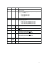
CVBS 35 O Analog video output
Determined by the state of CPNT pin and CR0[5:4]
CPNT CR0[5] CR0 [4]
--- 0 ---- X------ X: ---Composite video output
--- 1----- X------ 0: --- Cr output in CbCr component mode
--- 1 ---0 0------X: --- 11 111 1111 1- ::
--- 1------1------ 1: ----Blue color output in RGB mode
Y 31 O Analog video output
Determined by the state of CPNT pin and CR0[5:4]
CPNT CR0[5] CR0 [4]
--- 0 ----- X----- X: ---S-Video Y output.
--i 1------ X---- - 0: ---Cb output in CbCr component mode
--- 1 ---0 0------X: -- 1111 1111 11- ::
- i 1 ----- 1--- -- 1: - -R color output in RGB mode
C 33 O Analog video output
Determined by the state of CPNT pin and CR0[5:4]
CPNT CR0[5] CR0 [4]
--- 0 ------ X------X: --S-Video C output.
---- 1 ------ 1-----0:---Cb output in CbCr component mode
--1 1 ------ 0 ---- X:111 111 1- ::
--1 1 ------ 1------X:--Green color output in RGB mode
VREF 40 I/O Voltage reference. It has an internal voltage reference circuit, but may
be overridden by an external voltage reference input. A 0.1 uF ceramic
capacitor is required between this pin and GND.
IREF 39 I A resistor should be connected between this pin and GND to control the
DAC output current. The recommended value is 198 (382) ohm 1%
metal film resistor for double (single) end 75 ohm termination.
COMP 38 I Compensation capacitor for the DAC internal reference amplifier. A 0.1
uF ceramic capacitor is required between this pin and VDDA.
BIAS 37 I/O DAC bias voltage. A 0.1 uf ceramic capacitor must be used to de-
couple this pin to VDDA.
4-10