


Audio Expander Crestron Adagio™ AAE
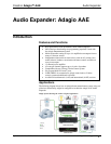
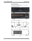
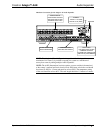
Adagio AAE Audio Expander-Rear View
5
6
9
3
7
8
4
NOTE: Cable connections can extend the overall depth of the AAE by
approximately two to three inches.
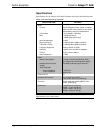
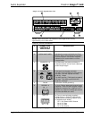
Connectors, Controls and Indicators
# CONNECTORS,
CONTROLS, &
INDICATORS
DESCRIPTION
1 ROOM BUTTONS Provided to select the room.
2 ROOM NAME LABEL
Indicates the rooms controlled by the Room
Buttons. White, LED backlighting, adjustable
via control system. Use Crestron Engraver
software to print custom labels or use the
included labels.
3 SOURCES 1-10
40 RCA female connections providing 10
unbalanced stereo line-level audio inputs and
parallel loop-throughs.
4 POWER INPUT
Fuse terminal and power connector.
The AAE requires a T8AH-type fuse rated at
250 Volts
1
. The AAE requires 120 VAC,
50-60 Hz, 7 Amps.
The AAEI requires a T4AH-type fuse rated at
250 Volts
1
. The AAEI requires 230 VAC,
50-60 Hz, 3.5 Amps
2
.
5 Ground
6-32 screw, chassis ground lug.
6 ROOMS 1-6
12, 2-pin 7.62mm detachable terminal blocks
(supplied). These are power amplifier outputs
designed to accept up to 12 AWG (4.0 mm
2
)
speaker wire. Output is 45 Watts per channel
at 8 ohms (60 Watts at 4 ohms).
7 NET 1-6
(6) Four-pin terminal blocks (supplied)
provide home run Cresnet
®
connections to
distribute power and Cresnet data to rooms
for keypads and/or APADs.
Pin 1 (24) Power 24VDC Cresnet
Pin 2 (Y) Data
Pin 3 (Z) Data
Pin 4 (G) Ground
(Continued on following page)
4 • Audio Expander: Adagio AAE Operations Guide – DOC. 6460A