


MVP-TDS Table Top Docking Station
3
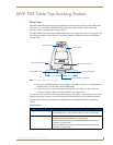
MVP-TDS Table Docking Station for MVP Panels
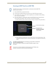
MVP-TDS LED Indicators
The two LED indicators indicate the battery and communication status:
Installation
Interface Connector Pins and Functions
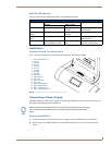
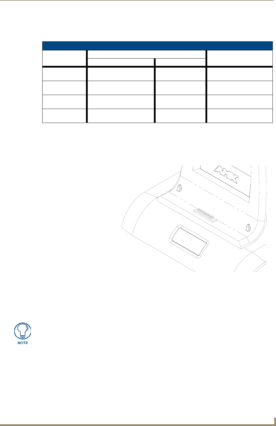
FIG. 3 gives the pin numbering and function information for the docking stations
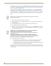
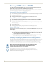
Connecting a Power Supply
The MVP-TDS uses a PS4.4 power supply (included with the MVP) to indirectly provide power to the
MVP panel, while charging internal batteries.
Powering the MVP-TDS
1.
Connect the terminal end of the PS4.4 power supply to the rear PWR connector on the TDS.
2. Provide power to the MVP-TDS by connecting the PS4.4 AC power cord to an external power
source.
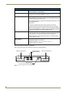
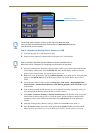
LED Pattern Indicators for the MVP-TDS
LED Left - Battery Status Right - Comm. Status
TDS only MVP in Cradle
Solid Bright TDS batteries are fully charged MVP batteries are fully
charged
MVP panel is docked and
communicating
Flashing Bright
(Slow)
TDS batteries are charging MVP batteries are
charging
N/A
Flashing Bright
(Fast)
N/A N/A MVP panel is docked but not
communicating
Solid Dim TDS receiving power but con-
tains no batteries in cradle
No batteries within the
MVP
MVP panel is NOT docked
and NOT communicating
FIG. 3
MVP-TDS Connector Pin locations and Pinout function
2
1
18
17
1 - Data - Panel Detect IN
2 - Ground
3 - not used
4 - Ground
5 - not used
6 - Ground
7 - not used
8 - not used
9 - not used
10 - DC Power
11 - Data - Receive
12 - DC Power
13 - Data - Transmit
14 - DC Power
15 - Data - USB Device D-
16 - Data - Cradle Detect
17 - Data - USB Device D+
18 - Data - Panel Detect OUT
Static electricity can damage electronic circuitry. Before touching the unit, discharge
any accumulated static electricity from your body by touching a grounded metal
object.