8
CHAPTER 3
Service LED (Red)
When blinking once every two seconds, the Service LED
indicates that the network hardware is operational, but the
loudspeaker is not installed (commissioned) on the network.
When a loudspeaker has been installed on the network
the, Service LED will be unlit and the Activity LED will ash
continuously.
NOTE: When continuously lit, the Service
LED indicates that the loudspeaker has had
a local RMS hardware failure. In this case, the RMS
communication module may be damaged and you
should contact Meyer Sound Technical support.
Service Button
Pressing the Service button will notify the corresponding
loudspeaker display icon on the RMS screen. When used in
combination with the Reset button, the card will be decom-
missioned from the network and the red Service LED will
blink.
Wink LED (green)
When lit, the Wink LED indicates that an ID signal has been
sent from the host station computer to the loudspeaker.
This is accomplished using the Wink button on the loud-
speaker Icon, Meter or Text views in the RMS monitoring
program.
Reset Button
Pressing the Reset button will cause the rmware code
within the RMS card to reboot. However, the commission-
ing state of the card will not change (this is stored in ash
memory). When used in combination with the Service But-
ton, the card will be decommissioned from the network and
the red Service LED will blink.
Activity LED (Green)
When the loudspeaker has been commissioned, the Activity
LED will ash continuously. When the Activity LED is unlit
the loudspeaker has not been installed on the network.
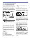
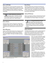
NOTE: The LEDs and buttons on the user
panel of the RMS communication board
shown back in gure 3.3 are used exclusively by
RMS, and have no effect on the acoustical and/or
electrical activity of the UPJ-1P itself – unless MUTE
or SOLO is enabled at the board and from the RMS
software.
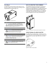
USER INTERFACE
The RMS software features an intuitive, graphical Windows
user interface. As mentioned earlier, each loudspeaker
appears on the computer’s color monitor as a “view” in
the form of a status icon, bar graph meter, or text meter
(numerical values), depending on your preferences.
Each view contains loudspeaker identi-
cation and data from the unit's amplier,
controller, drivers and power supply.
System status conditions cause chang-
es in icon and bar graph indicators,
alerting the operator to faults or exces-
sive levels. The views are moveable and
are typically arranged on the screen to
reect the physical layout of the loud-
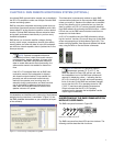
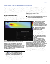
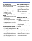
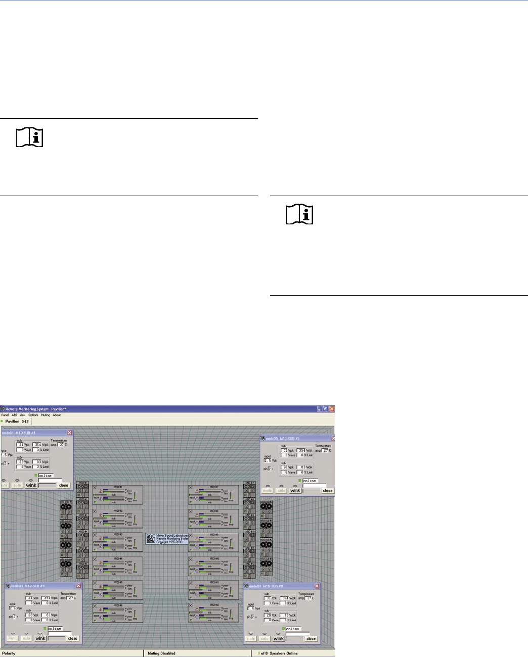
speakers. You can design a screen
“panel” of icons or meters, as shown in
Figure 3.4, and save it on the computer’s
hard disk, with the panel conveniently
named for a unique arrangement or
performer.
If the installation pattern changes com-
pletely, a new screen panel can be built.
If a subset of installed loudspeakers will
be used for a subsequent event, only
selected loudspeakers need to appear
on screen for that performance.
Figure 3.4: Sample RMS display panel