3. General specifications
3-2
,)& )$!"
3.2.1 Fnet master module structure
: K7F-FUEA, K7F-FUOA, K4F-FUEA, K3F-FUEA
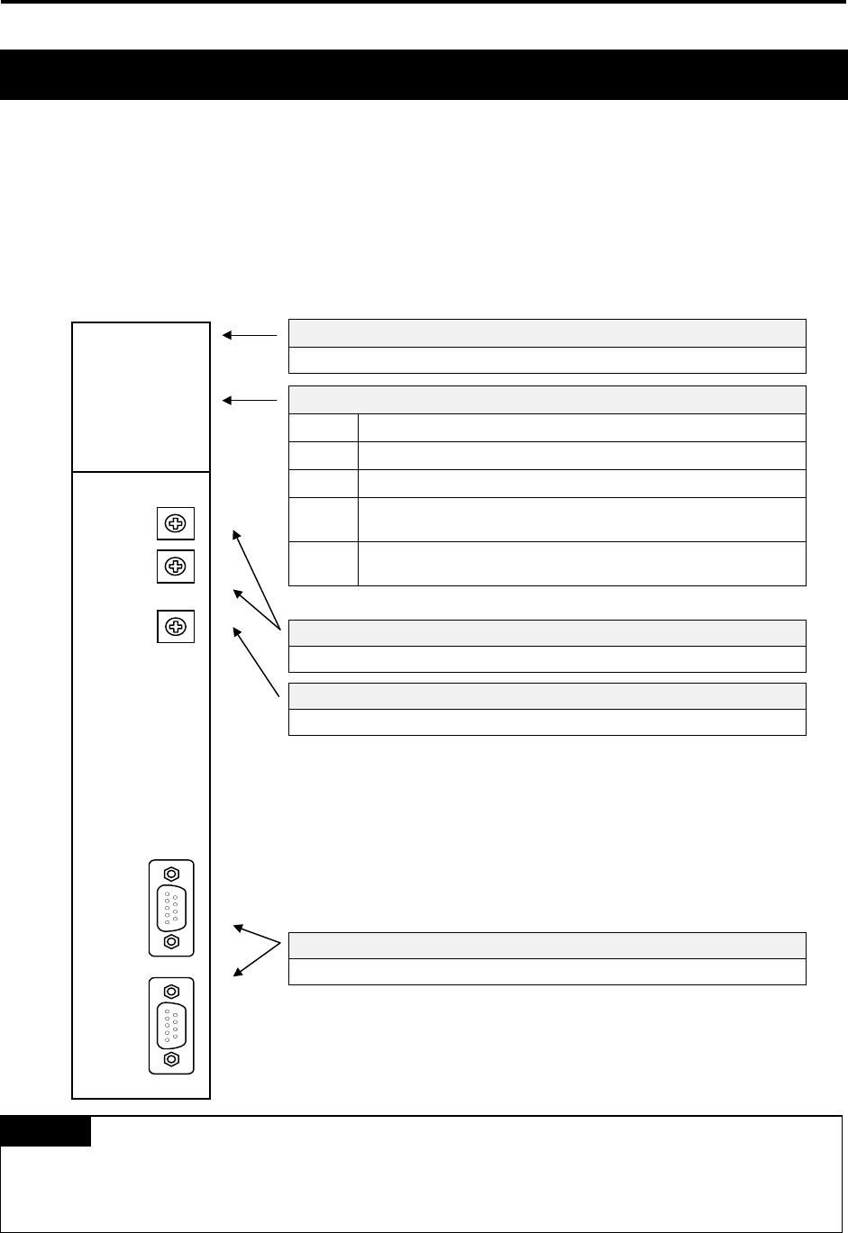
1) K7F-FUEA, K7F-FUOA, K4F-FUEA
Type name indicating section
Indicates type name of communication module
LED indicating section
RUN Indicates the status of CPU module and interface
LAS Indicates that communication module is performing LAS function.
TOKEN Indicates whether communication module has a token or not.
Tx/Rx Indicates whether communication module is transmitting/ receiving
or not.
FAULT Flickers when the error that normal operation is not possible
occurred in communication module
Station number setting switch
Sets station number in the range of 0~63 station(Use decimal).
Mode setting switch
Sets operation mode of communication module
Communication connector
Connector for electric cable connection to connect communication module.
1. In the figure shown above, connector of K7F-FUOA is made of optical connector.
2. For mode setting switch, see 3.2.6 Fnet mode setting.
Remark
3.2 Structure and configuration
