Page 23
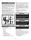
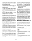
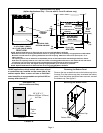
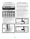
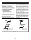
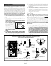
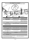
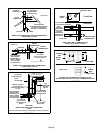
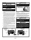
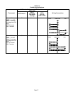
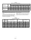
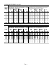
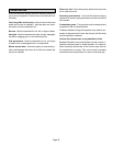
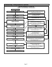
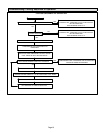
TYPICAL AIR INTAKE PIPE CONNECTIONS
UPFLOW OR DOWNFLOW DIRECT VENT APPLICATIONS
(Right−Hand Exit in Upflow Application Shown)
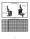
FIGURE 25
PLUG
(Must be
glued in
place)
*Limit pipe length to 4" in G61MP−110,
−111, −135 applications.
−36B−045−
−36B−070
−36B−071
−48C−090
−60C−090
−60C−091
−36B−045
−36B−070
−36B−071
−48C−090
−60C−090
−60C−091
−48C−110
−60C−110
−60C−111
−36B−045
−36B−070
−36B−071
−48C−090
−60C−090
−60C−091
−48C−110
−60C−110*
−60C−111*
−60D−135*
2
2
2
2
2
2
2−1/2",
3" OR
4
TRANSITION
*2"
TRANSITION
2−1/2",
3" OR
4
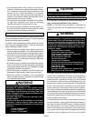
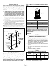
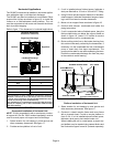
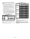
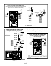
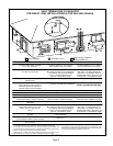
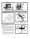
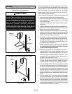
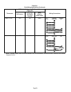
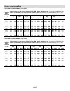
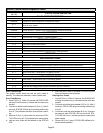
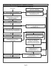
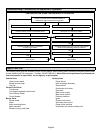
FIGURE 26
TYPICAL AIR INTAKE PIPE CONNECTIONS
HORIZONTAL DIRECT VENT APPLICATIONS
(Horizontal Right−Hand Air Discharge Application Shown)
*2”
2”
2”
2”
TRANSITION
TRANSITION
2”
2−1/2”,
3” OR 4”
2−1/2”,
3” OR 4”
*Limit pipe
length to 4" in −110, −111,
−135 applications.
2”
−36B−045
−36B−070
−36B−071
−48C−090
−60C−090
−60C−091
−48C−110
−60C−110*
−60C−111
−60D−135*
−36B−045
−36B−070
−36B−071
−48C−090
−60C−090
−60C−091
−48C−110
−60C−110
−60C−111
−36B−045
−36B−070
−36B−071
−48C−090
−60C−090
−60C−091
2”
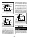
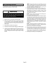
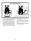
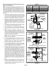
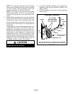
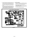
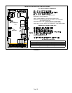
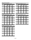
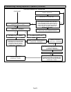
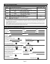
Follow the next three steps when installing the unit in Non-
Direct Vent applications where combustion air is taken
from indoors and flue gases are discharged outdoors.
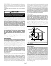
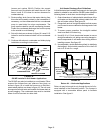
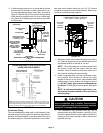
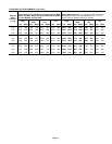
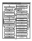
FIGURE 27
PLUG
(Must be
glued in
place)
TYPICAL AIR INTAKE PIPE CONNECTIONS
UPFLOW OR HORIZONTAL NON−DIRECT
VENT APPLICATIONS
(Right−Hand Exit in Upflow Application Shown)
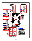
6 in. Max.
INTAKE
DEBRIS
SCREEN
(Provided)
NOTE − Debris screen and elbow may be rotated, so that
screen may be positioned to face forward, backward or
downward.