2-11
MTPX Plus Twisted Pair Matrix Switchers • Installation
Front Panel Configuration Port
AUDIO
VIDEO
I/O
CONTROL
ENTERPRESET
VIEW
ESC
MTPX PLUS SERIES SWITCHER
CONFIG
13
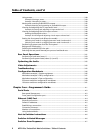
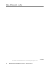
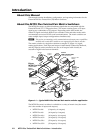
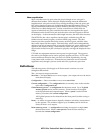
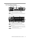
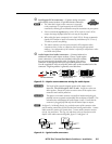
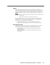
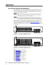
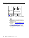
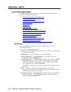
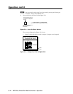
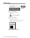
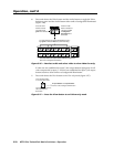
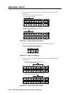
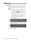
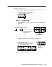
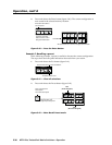
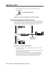
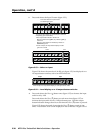
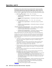
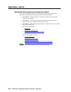
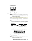
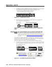
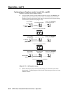
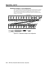
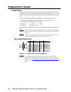
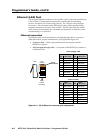
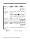
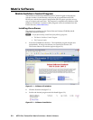
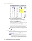
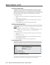
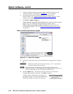
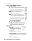
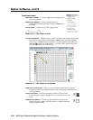
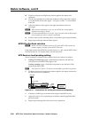
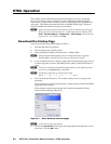
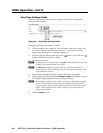
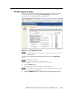
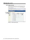
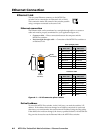
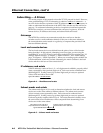
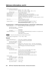
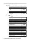
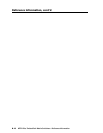
Figure 2-11 — Front panel configuration port
m
Configuration port — This 2.5 mm mini stereo jack serves the same serial
communications function as the rear panel Remote port, but it is easier
to access than the rear port after the matrix switcher has been installed
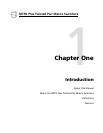
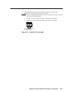
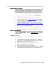
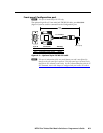
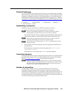
and cabled. The optional 9-pin D to 2.5 mm mini jack TRS RS-232 cable,
part #70-335-01 (figure 2-12), can be used for this connection.
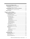
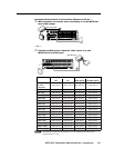
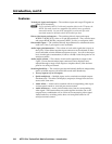
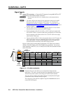
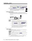
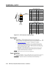
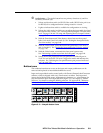
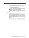
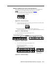
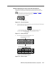
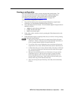
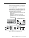
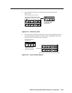
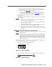
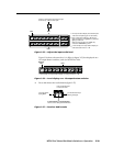
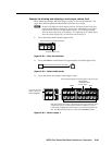
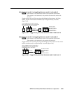
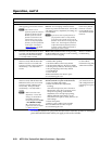
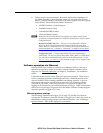
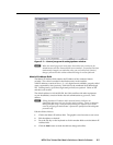
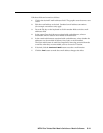
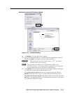
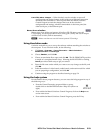
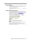
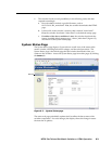
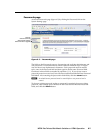
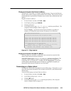
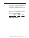
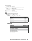
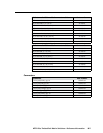
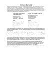
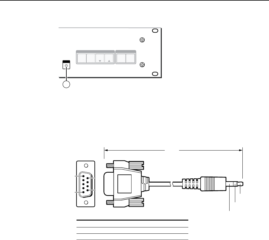
6 feet
(1.8 m)
Part #70-335-01
5
1
9
6
Sleeve (Gnd)
Ring
Tip
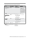
9-pin D Connection TRS Plug
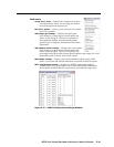
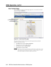
Pin 2 Computer's RX line Tip
Pin 3 Computer's TX line Ring
Pin 5 Computer's signal ground Sleeve
Figure 2-12 — Optional 9-pin TRS RS-232 cable
N
ThisportisindependentoftherearpanelRemoteportandisnotaffectedby
changestotherearpanelport’sprotocol.Thisfrontpanelport’sprotocolcanbe
changed,underSIScommandcontrolonly.SeetheCommand/Responsetable
forIPSIScommands,inchapter4,“Programmer’sGuide”,tocongureall
portsunderSIScontrol.
N
AfrontpanelCongurationportconnectionandarearpanelRemoteport
connection can both be active at the same time.
This port is RS-232 only, with its default protocols as follows:
• 9600baud • noparity • 8databits
• 1stopbit • noowcontrol
N
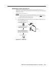
The maximum distances from the matrix switcher to the controlling device can
varyupto200'(61m).Factorssuchascablegauge,baudrates,environment,
and output levels (from the switcher and the controlling device) all affect
transmission distance. Distances of about 50' (15 m) are typically not a problem.
Insomecasesthematrixswitchermaybecapableofserialcommunicationsvia
RS-232upto250'(76m)away.