Installation, cont’d
MTPX Plus Twisted Pair Matrix Switchers • Installation
2-6
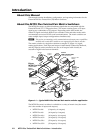
The audio level for each local input can be individually set via the front panel
or serial port control to ensure that the level on the output does not vary from
input to input. See chapter 3, “Operation”, chapter 4, “Programmer’s Guide”,
chapter 5, “Matrix Software”,andchapter6,“HTMLOperation”, for details.
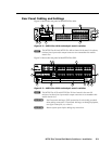
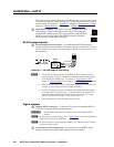
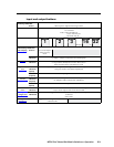
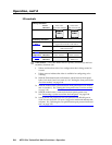
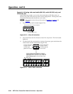
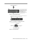
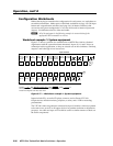
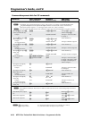
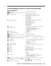
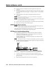
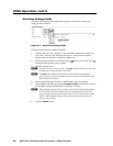
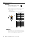
d
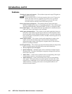
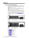
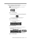
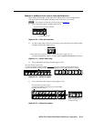
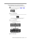
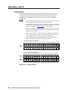
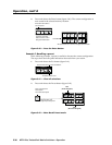
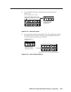
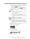
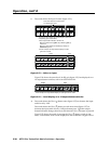
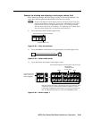
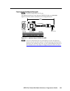
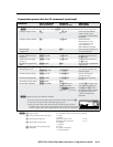
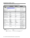
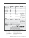
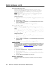
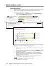
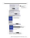
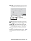
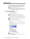
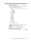
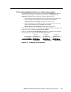
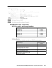
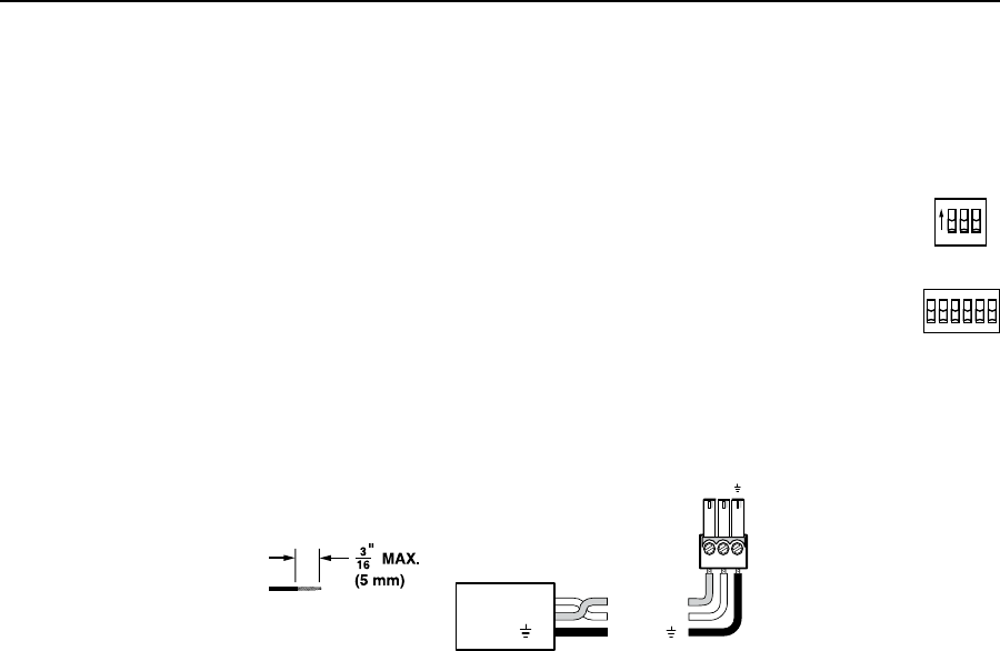
Input Select switches —Forinputs1through3(matrixsizes1616
andsmaller)orinputs1through6(matrixsizes1632andlarger),
set these DIP switches to the Local (up) position to select the local
(RGB video and audio) input. Set the DIP switches to the RJ-45
(down) position to select the MTP input.
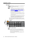
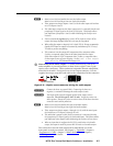
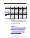
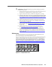
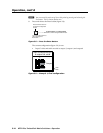
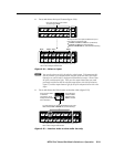
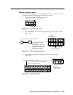
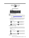
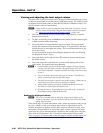
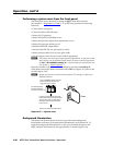
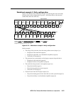
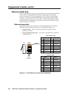
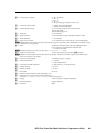
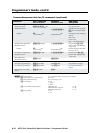
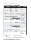
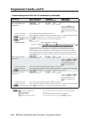
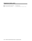
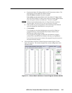
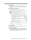
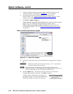
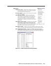
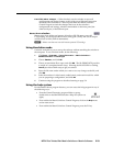
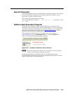
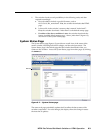
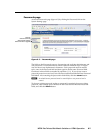
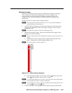
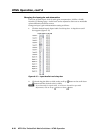
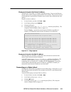
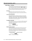
RS-232 output inserts
e
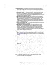
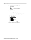
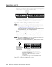
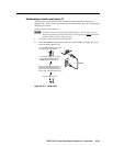
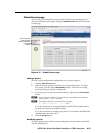
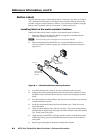
RS-232 Output Insert connectors — For bidirectional RS-232 data that is
routed to a specific (unswitchable) TP output, connect a serial device to one of
these 3.5 mm, 3-pole captive screw connectors. Figure 2-7 shows how to wire
the connectors.
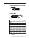
Receive (Rx)
Transmit (Tx)
Ground ( )
Bidirectional
RS-232
Device
Ground ( )
Receive (Rx)
Transmit (Tx)
RxTx
Do not tin the wires!
Figure 2-7 — RS-232 output insert wiring
N
• FortheRS-232OutputInserttobeavailableontheTPoutput,theinsert
mustbeenabledviaanSIScommand,theWindows-basedcontrolprogram,
oranMTPXPlusHTMLpage.Seechapter4,“Programmer’sGuide”,
chapter5,“MatrixSoftware”,andchapter6,“HTMLOperation”fordetails.
• WhenanRS-232outputinsertisenabled,anycontentontheaudio/RS-232
wire pair for the TP input tied to that output is disabled.
• EachRS-232outputinsertionisdedicatedtotheoutputwiththatnumber;
forexample,RS-232OutputInsert1isalwaysroutedtotheOutput1TP
connector(whenenabledasdescribedinthenoteabove),RS-232Output
Insert2isroutedtotheOutput2TPconnector,andsoon.
• TheswitchtimefortheRS-232outputinsertis50ms.
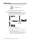
Signal outputs
f
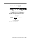
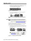
Outputs (MTP) connectors — Connect the TP inputs of compatible MTP or
VTT receivers to these RJ-45 female connectors.
C
Do not connect this device to a computer data or telecommunications
network
N
SeetheInputsconnector,item
a
,inthe“Signalinputs”section,fordetailedpin
assignmentsfortheRJ-45connectors.
N
For best results, use a cable length of at least 50' (15 m) between the TP output
connector and the receiver.
g
Local Outputs (VGA) connector(s) — Connect one or two RGBHV video
displays to these 15-pin HD female connectors for each output.
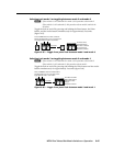
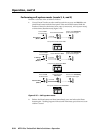
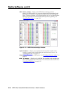
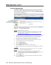
INPUT SELECT
ON
LOCAL
RJ - 45
123
LOCAL
RJ-45