Effective December, 1998
IL 33-FC6-1
Page 5
Step 6: Mounting the Aux. CT Platform
Assembly
A. Working from the front of the Breaker, remove
and discard the two bolts located near the top
and middle of the right Breaker Rear Channel.
Align the Aux. CT Platform Assembly as
shown. Using the .375-16 × 1.50" bolt, lock
washer, and flat washer (top) and the
.312-18 × 1.50" bolt, lock washer, and flat
washer (bottom) mount the Aux. CT Platform
Assembly to the Breaker. The Aux. CT
Harness must be routed behind the assembly,
emerging at the bottom.
B.
For Kits Supplied with a PT Module Only
.
Route the PT Wires behind the Aux. CT
Platform Assembly, then down the back wall
of the Breaker. They should be routed so that
they are clear of all moving parts within the
Breaker.
The PT Wires are marked for connection to
Phases 1, 2, and 3 with corresponding
numbers.
NOTE: Before cutting the PT Wires, verify the
Phase Convention used on this Breaker
Application.
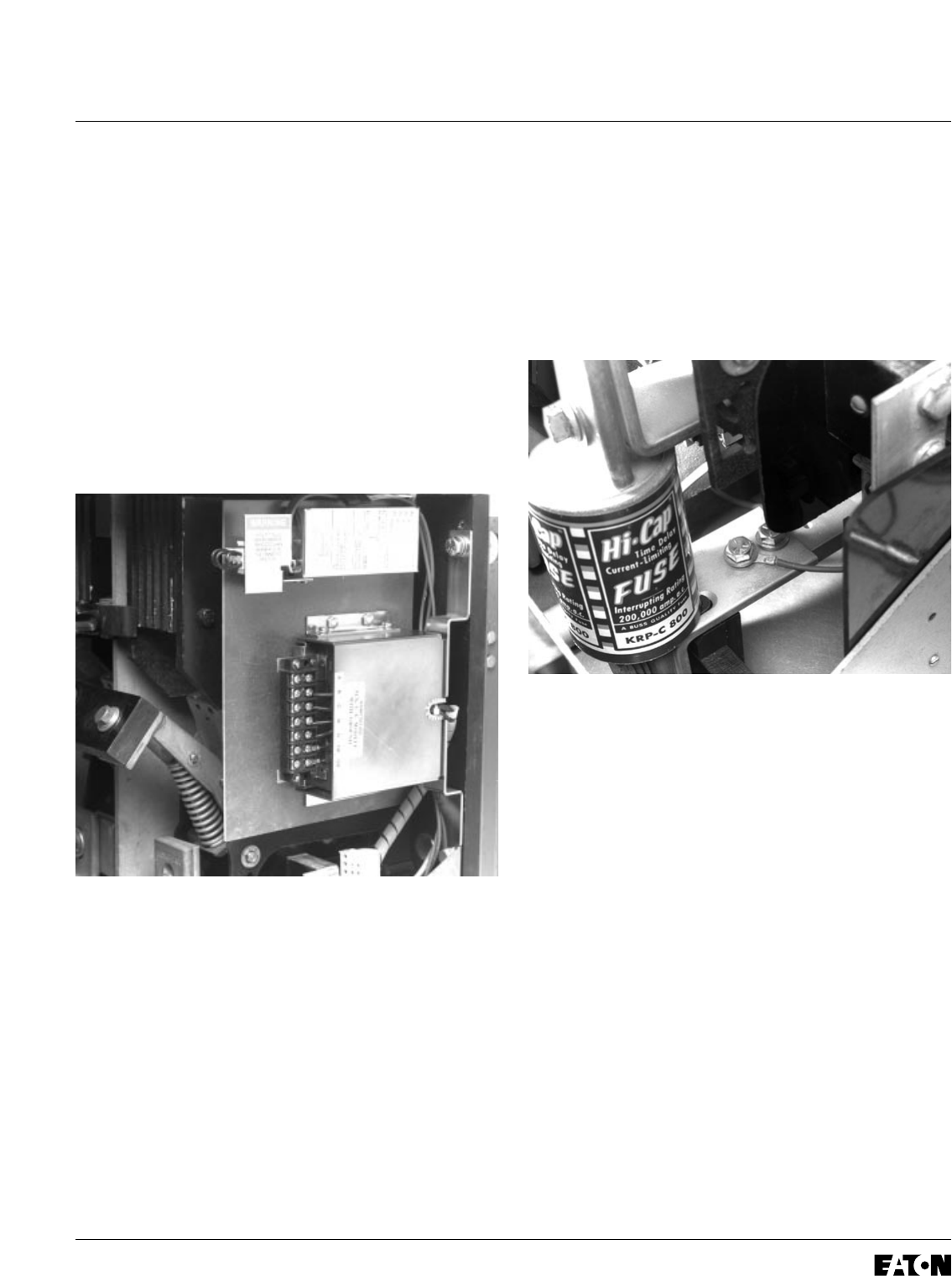
Route the PT Wires to a position suitable for
attachment to the bottom fuse mounting
brackets. Move the PT Wire markers to a
position where they will still be attached to
the wires after cutting. Cut the wires to length,
strip each wire .250", and install the correct
size ring terminal for the bolt used for the
connection.
Using one of the original bottom fuse mounting
bracket bolts, attach each PT Wire to its
corresponding phase.
Step 7: Installing the Trip Unit on the Trip Unit
Mounting Bracket
A. Insert the Brass Spacers provided in the
notches at the rear of the Trip Unit. Using the
.190-32 × 4.00" screws, flat washers, lock
washers, and hex nuts provided, mount the
Trip Unit to the Mounting Bracket. Note that
the screws are inserted from the top of the
Trip Unit.
B. Using the .138-32 × 375" screws, flat
washers, lock washers, and hex nuts provided,
mount the Trip Unit Support Clips to each side
of the Trip Unit Mounting Bracket as shown.
The Support Clips must be installed so that
they engage the slots in the sides of the
Trip Unit.