


Contents
vi
Figures
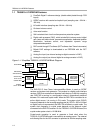
1−1 Simplified TAS5010−5112F2EVM Block Diagram 1-2. . . . . . . . . . . . . . . . . . . . . . . . . . . . . . . . . .
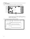
2−1 Board Outline With Connectors, Switches, Jumpers, and Indicators 2-2. . . . . . . . . . . . . . . . . .
2−2 Physical Structure for the TAS5010−5112F2EVM 2-2. . . . . . . . . . . . . . . . . . . . . . . . . . . . . . . . . .
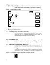
2−3 Default Jumper Positions 2-4. . . . . . . . . . . . . . . . . . . . . . . . . . . . . . . . . . . . . . . . . . . . . . . . . . . . . . .
2−4 Pin Numbers at the Line Input/Output Connector (Top View) 2-4. . . . . . . . . . . . . . . . . . . . . . . .
2−5 Pin Numbers at the Parallel Port/I
2
C Interface/I
2
C (J300) 2-5. . . . . . . . . . . . . . . . . . . . . . . . . . .
2−6 Pin Numbers at PSU Connector (Top View) 2-6. . . . . . . . . . . . . . . . . . . . . . . . . . . . . . . . . . . . . . .
3−1 Recommended Power-Up and Power-Down Sequence 3-2. . . . . . . . . . . . . . . . . . . . . . . . . . . .
3−2 EVM Board Connected to S/PDIF Sources and Personal Computer 3-3. . . . . . . . . . . . . . . . .
Tables
2−1 Description of J160 and J170 2-5. . . . . . . . . . . . . . . . . . . . . . . . . . . . . . . . . . . . . . . . . . . . . . . . . . .
2−2 Description of J300 2-5. . . . . . . . . . . . . . . . . . . . . . . . . . . . . . . . . . . . . . . . . . . . . . . . . . . . . . . . . . . .
2−3 Description of Loudspeaker Connectors 2-6. . . . . . . . . . . . . . . . . . . . . . . . . . . . . . . . . . . . . . . . . .
2−4 Description of PSU Connector 2-6. . . . . . . . . . . . . . . . . . . . . . . . . . . . . . . . . . . . . . . . . . . . . . . . . .
3−1 Maximum Supply Voltage (Single Supply) 3-2. . . . . . . . . . . . . . . . . . . . . . . . . . . . . . . . . . . . . . . .
3−2 Maximum H-bridge Voltage vs Load Impedance 3-2. . . . . . . . . . . . . . . . . . . . . . . . . . . . . . . . . . .