


Description of Connectors
2-5
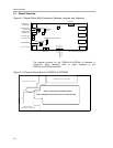
Detailed Description of the EVM
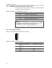
Table 2−1. Description of J160 and J170
Pin No. Description
Analog Input Connector (J160)
1 Left Channel Input
2 Ground
3 Right Channel Input
Analog Output Connector (J170)
1 Left Channel output
2 Ground
3 Right Channel Output
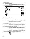
2.4.4 PC and I
2
C Interface (J300)
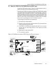
The PC interface using the attached special cable to parallel/printer port on the
PC. This makes it possible to control the TAS3002 digital audio processor
totally from the PC using the special DCT software saved on the PurePath
Digitalt amplifier CD-ROM.
The PC interface can also be used to control the TAS3002 from an external
microcontroller of your own choice.
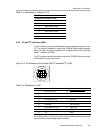
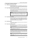
Figure 2−5. Pin Numbers at the Parallel Port/I
2
C Interface/I
2
C (J300)
9
1
34
2
56
78
Table 2−2. Description of J300
Pin No. Pin Description I/O Net Name on Schematic
1 Power ON Reset O POWER−ON−RESET
2 Serial Data Line (SDA) I/O SDA−BI
3 Serial Clock Line (SCL) I/O SCL−BI
4 Serial Data Line In I SDA−IN
5 Serial Clock Line Out O SCL−OUT
6 Reserved − For future use
7 Serial Data Line Out O SDA−OUT
8 Serial Clock Line In I SCL−IN
9 0 V − GND
Pin 2 (SDA) and pin 3 (SCL) are used for communication between an external
micro-controller and the digital audio processor.