


51
MZ-N1
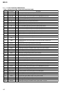
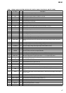
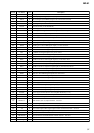
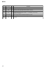
Pin No.
Pin Name
I/O Description
195 ADDT
I
Data input from the external A/D converter
196 LRCK O L/R sampling clock signal (44.1KHz) output to the external A/D converter
197 XBCK O Bit clock signal (2.8224MHz) output to the external A/D converter
198 FS256
O
11.2896MHz clock signal output to the external A/D converter
199 NC
I
Clock signal input from the external VCO Not used
200 DVSS3
—
Ground terminal (for the DSP block)
201 DVDD3
—
Power supply terminal (for the DSP block) (+1.1V)
202 ADFG
I
ADIP duplex FM signal (20.05±1kHz) input from the RF amplifier
203 NC
O
Filter cut off control signal output terminal Not used
204 IFVDD3
—
Power supply terminal (for the microcomputer I/F block) (+1.7V)
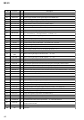
205 IFVSS3
—
Ground terminal (for the microcomputer I/F block)
206 APCREF O Reference PWM signal output for the laser automatic power control to the RF amplifier
207 TRDR O Tracking servo drive PWM signal output (–) to the coil driver
208 TFDR O Tracking servo drive PWM signal output (+) to the coil driver
209 FFDR O Focus servo drive PWM signal output (+) to the coil driver
210 FRDR O Focus servo drive PWM signal output (–) to the coil driver
211 FS4 O 176.4kHz clock signal output to the power control
212 SPRD O Spindle motor drive control signal output (U) to the motor driver
213 SPFD O Spindle servo drive PWM signal output to the motor driver
214 SPDV O Spindle motor drive control signal output (V) to the motor driver
215 SPDW O Spindle motor drive control signal output (W) to the motor driver
216 SPCU I Spindle motor drive comparison signal input (U) from the motor driver
217 SPCV I Spindle motor drive comparison signal input (V) from the motor driver
218 SPCW I Spindle motor drive comparison signal input (W) from the motor driver
219 SRDR O Sled motor drive control signal output (U) to the motor driver
220 SFDR O Sled servo drive PWM signal output to the motor driver
221 SLDV O Sled motor drive control signal output (V) to the motor driver
222 SLDW O Sled motor drive control signal output (W) to the motor driver
223 DVSS4
—
Ground terminal (for the DSP block)
224 DVDD4
—
Power supply terminal (for the DSP block) (+1.1V)
225 SLCU I Sled motor drive comparison signal input (U) from the motor driver
226 SLCV I Sled motor drive comparison signal input (V) from the motor driver
227 SLCW I Sled motor drive comparison signal input (W) from the motor driver
228 IFVDD4
—
Power supply terminal (for the microcomputer I/F block) (+1.7V)
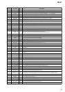
229 IFVSS4
—
Ground terminal (for the microcomputer I/F block)
230 EFMO O EFM encode data output for the record to the over write head drive
231 to
233
MNT0 to 2 O DSP monitor (0) to (2) output terminal Not used
234 MNT3 O Off track signal output from the DSP monitor (3)
235 SENSE O DSP internal status (DSP SENS monitor) signal output terminal Not used
236 TX O Record data output enable signal output monitor terminal of the DSP Not used
237 RECP O Laser power changeover signal output terminal Not used
238 LRCKI/XELT
I
Input terminal for the PCM data I/F/ ATRAC data I/F Not used
239 XBCKI/ECK
I
Input terminal for the PCM data I/F/ ATRAC data I/F Not used
240 DATAI/EDT
I
Input terminal for the PCM data I/F/ ATRAC data I/F Not used
241 XERQ
I
Input terminal for the ATRAC data I/F Not used