Connections
18 - English
Method 4 : Connecting to
Component video input
jacks(Y,C
B/TB,CR/PB) in 480p mode
Your TV must support progressive scan input to allow you to
watch 480p video output.
1. Connect Component video cables(not supplied) between
the COMPONENT VIDEO OUT jacks on DVD Recorder-
VCR and COMPONENT VIDEO IN jacks on the TV (or
AV amplifier).
2. Press the Progressive button on the front panel. The mes-
sage “Press “Yes” to confirm Progressive scan mode.
Otherwise press “No”.” will be displayed. If you want
480P mode, select yes. If “480P” is displayed on the front
panel display, now your DVD Recorder-VCR is operated on
480P Mode. Make sure that the disc has stopped complete-
ly before changing the mode.
COMPONENT
VIDEO OUT
Y
C
B
/P
B
C
R
/P
R
OUT
RF
(TO TV)
DIGITAL AUDIO OUT
AUDIO OUT
COMPONENT
VIDEO OUT
OPTICAL
COAXIAL
RY
C
B
/P
B
C
R
/P
R
L
R
AUDIO AUDIO
LINE OUT LINE IN 1
VIDEO VIDEO
L
R
L
IN
(FROM ANT.)
RF
R
L
R
L
Make sure that the color coded connections match.
That is, the Y, Pb and Pr component output jacks
of your DVD Recorder-VCR should be connected
to the exact corresponding component input jacks
on your TV. Otherwise, red or blue images will be
displayed on the TV screen.
Once 480p video output mode is selected, Video,
S-Video and 480i outputs are disabled.
Make sure that the left and right audio output
jacks of your DVD Recorder-VCR are connected to
the left and right audio input jacks of your TV,
respectively.(page 19)
Note
There are several ways to connect your DVD Recorder-VCR.
Select the audio connection that best suits you below.
•
Method 1 : Connecting to your TV
•
Method 2 : Connecting to a stereo amplifier (analog audio
out / digital audio out)
•
Method 3 : Connecting to an AV amplifier with a digital
input jack.
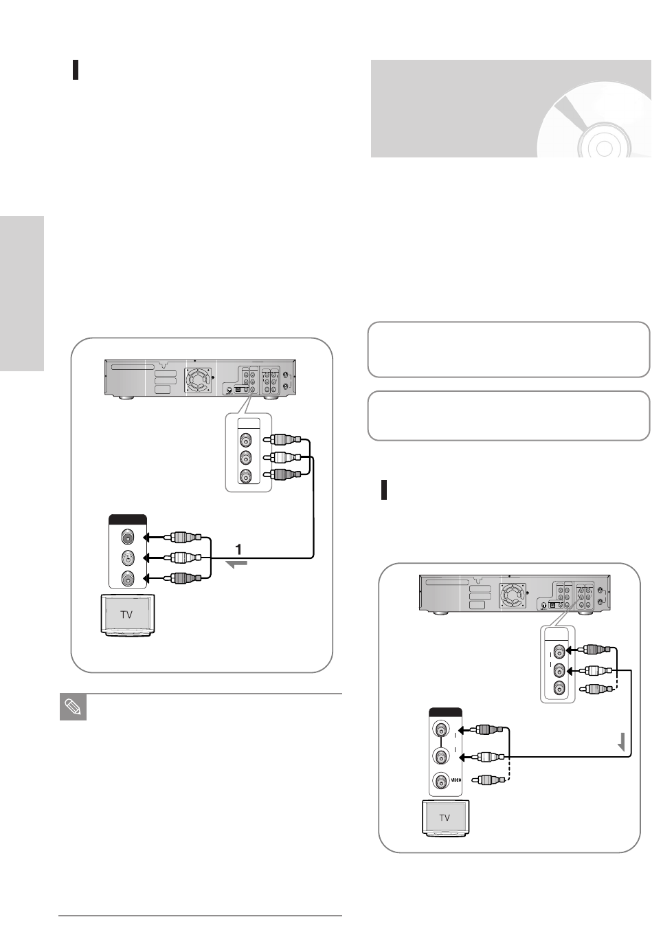
Step 4 : Connecting
the Audio Cable
Manufactured under license from Dolby Laboratories.
“Dolby” and the double-D symbol are trademarks of
Dolby Laboratories.
“DTS” and “DTS Digital Out” are trademarks of
Digital Theater Systems, Inc.
Method 1 : Connecting to your TV
This connection will use your TV’s speakers.
OUT
RF
(TO TV)
DIGITAL AUDIO OUT
AUDIO OUT
COMPONENT
VIDEO OUT
OPTICAL
COAXIAL
RY
C
B
/P
B
C
R
/P
R
L
R
AUDIO AUDIO
LINE OUT LINE IN 1
VIDEO VIDEO
L
R
L
IN
(FROM ANT.)
RF
R
L
R
L
INPUT
AUDIOAUDIO
L
R
red
white
R
AUDIO
VIDEO
L
LINE OUT
L
red
white


