


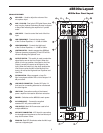
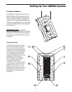
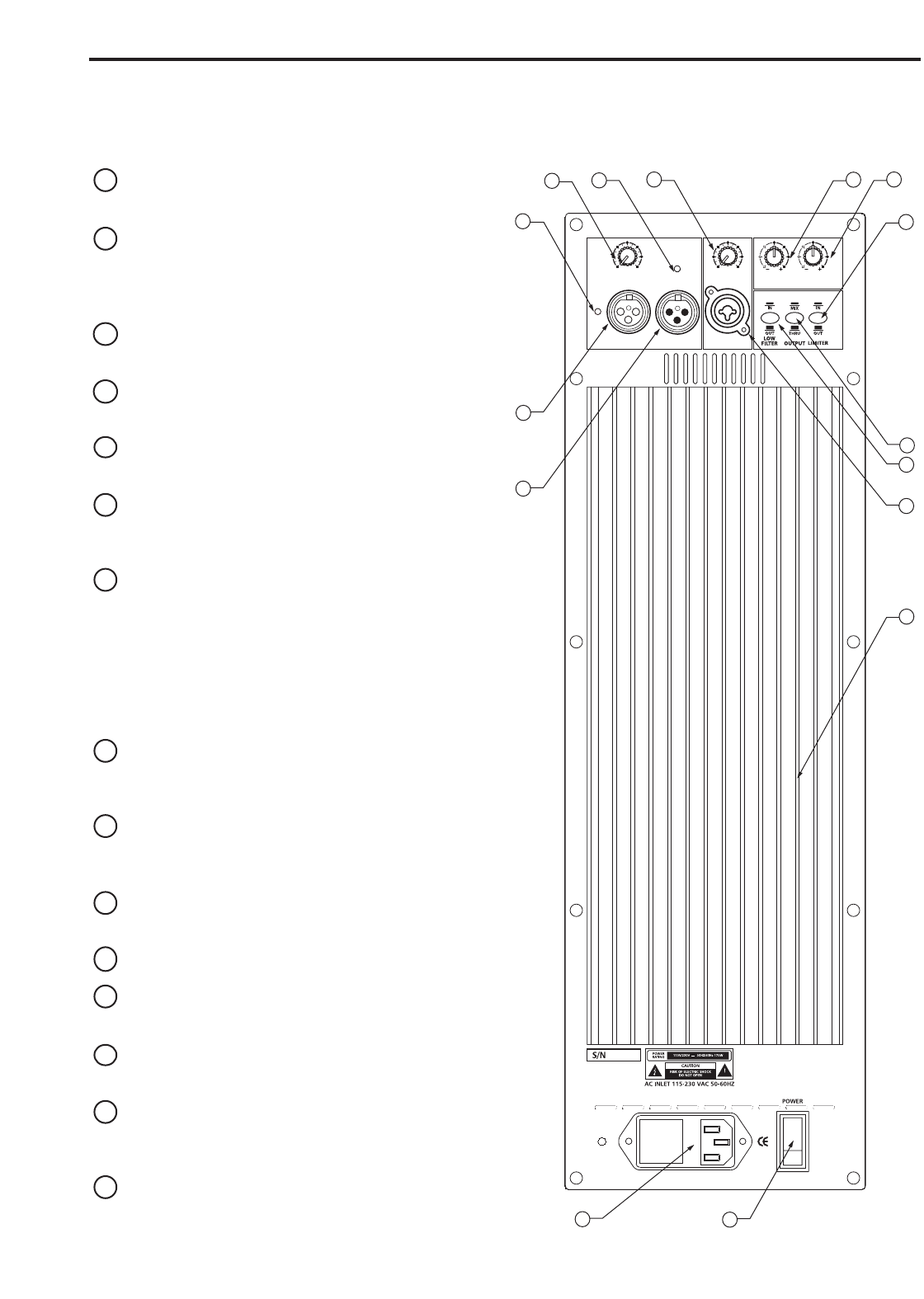
dB500a REAR PANEL
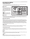
1 MIC LEVEL – Used to adjust the volume of the
microphone input.
2 AMP / CLIP LED - Dual color LED lights Green when
amp is active, flashes Red when the amp is clipped
or stays Red indicating the amplifier is in protect
mode.
3 LINE LEVEL – Used to control the level of the line
input.
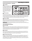
4 LOW FREQUENCY - Controls the low band
of the Channel Equalizer, +/- 12 dB at 100Hz.
5 HIGH FREQUENCY - Controls the high band
of the Channel Equalizer, +/- 12 dB at 10kHz.
6 LIMITER SWITCH - Used to engage the dB500a’s
Optimax dynamics processing. A red LED will illu-
minate indicating the Optimax is on.
7 OUTPUT SWITCH - This switch is used to select the
signal that is sent to the Line Output. When the
switch is in the up position, the signal on the Line
Output is exactly the same as the signal on the
Input. When the switch is in the down position the
Line Output carries the MIX of the Mic and Line
Inputs, as well as the High and Low Equalizer and
Low Filter.
8 FILTER SWITCH - When engaged, a Low-Cut
filter is employed at 80Hz with a roll-off slope of 12
dB per octave.
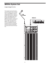
9 LINE INPUT CONNECTOR - Combo XLR plus 1/4
inch Input for connecting balanced or unbalanced
line level signals.
10 HEAT SINK - Convection cooling of the internal
power amplifier via massive aluminum extrusion.
11 POWER – Switches on the dB500a’s main power.
12 AC POWER INLET – Connect the supplied
standard IEC AC power cable here.
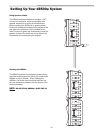
13 LINE OUTPUT - Male XLR connector used to link
multiple dB500a’s.
14 MIC INPUT CONNECTOR - XLR Input for connecting
low impedance microphones to the Low-Noise pre-
amp and Phantom Power.
15 PEAK LED- Red LED illuminates when the Mic input
receives a clipped signal.
5
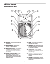
dB500a Layout
PROTECTION
DESIGNED AND ENGINEERED IN THE UNITED STATES BY SAMSON TECHNOLOGIES
www.samsontech.com
dB500A
MADE IN CHINA
SAMSON
MIC LEVEL
010
AMP / CLIP
LINE OUTPUTMIC INPUT LINE INPUT
LINE LEVEL
0
10
12 1212 12
8888
4444
EQUALIZER
LOW 100Hz HIGH 10KHz
PEAK
1
2
3
4
5
6
8
9
11
13
14
10
12
15
7
dB500a Rear Panel Layout