


9
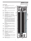
Operating the dB500a
Controls and Functions - continued
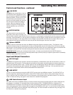
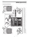
LOW FILTER
The dB500a also incorporates a Low-cut
FILTER which when engaged will roll off
the low frequency response of the cabinet
beginning at 80Hz. The low cut FILTER is
two pole, which means that the low fre-
quency roll off will gradually cut more and
more of the low frequencies (12dB per
octave). When you press the FILTER
switch in, the green LED will illuminate
indicating that the Low-cut FILTER is
engaged.
OUTPUT SWITCH
The Output switch is used to select the
signal that is sent to the Line Output. You
can have either a parallel output directly from the Line input, or a mixed signal including the Mic and line inputs plus the EQ
and limiter. When the switch is in the up position, the signal on the Line Output is exactly the same as the signal on the Line
Input. When the switch is in the down position the Line Output carries the MIX of the Mic and Line Inputs. If the Level con-
trols, High and Low Equalizer and Filter are used, they will also effect the signal sent to the Line Output.
Optimax LIMITER
In order to keep the sound loud and clean, the dB500a incorporates Optimax multi-band Limiting. The Optimax Limiter
divides the frequency range into separate parts so they can independently react to the limiting circuit. This ensures that the
high energy for the low frequency of a bass drum doesn’t cause the vocals to be over compressed. When you press the LIM-
ITER switch in, the red LED will illuminate indicating that the Optimax dynamics processing is engaged.
IMPORTANT NOTE: Unless you are using an external limiter, it is highly recommended that the LIMITER switch be
engaged at all times. This will ensure the cleanest possible output, and will protect your speaker system when it accidentally
receives a clipped signal from your mixer.
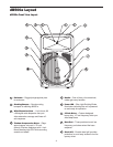
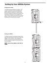
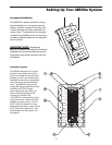
Input and Output Connectors
MIC XLR Input
The dB500a’s microphone input accepts a standard low impedance (150-600 Ohms) input and the connection is made via a
standard female XLR connector. The microphone input features a high quality, discrete transistor pre-amp providing trans-
parency and extended dynamic range. The MIC input can work simultaneously with the LINE input so it is possible to use a
microphone while playing alone with a keyboard that is plugged into the dB500a’s LINE input. You can control the micro-
phone input by using the MIC LEVEL control as described in the section below.
LINE OUTPUT
You can run several monitors by using the LINE OUTPUT to daisy-chain one dB500a to another. The LINE OUTPUT is a
balanced output that, depending on the position of the OUTPUT switch,will have either a direct parallel output of the LIne
input, or the Mix of the Line and Mic input. For more information on the Output switch, see section 8 above. For more infor-
mation on cables and wiring, see page 14 of this manual for a detailed wiring diagrams.
LINE Combo Balanced Input
For added convenience, the dB500a employs a Combo connector that accepts a standard XLR mic cable for balanced line
level signals, or a standard 1/4" instrument cable for either balanced (TRS – TIP/RING/SLEEVE) or unbalanced (TS –
TIP/SLEEVE) line level signals. The LINE input can work simultaneously with the Mic input so it is possible to use a micro-
phone while playing alone with a keyboard that is plugged into the dB500a’s LINE input. You can control the LINE input by
using the LINE LEVEL control as described in the previous page. For more information on cable and wiring, see page 14 of
this manual for a detailed wiring diagrams
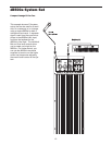
7
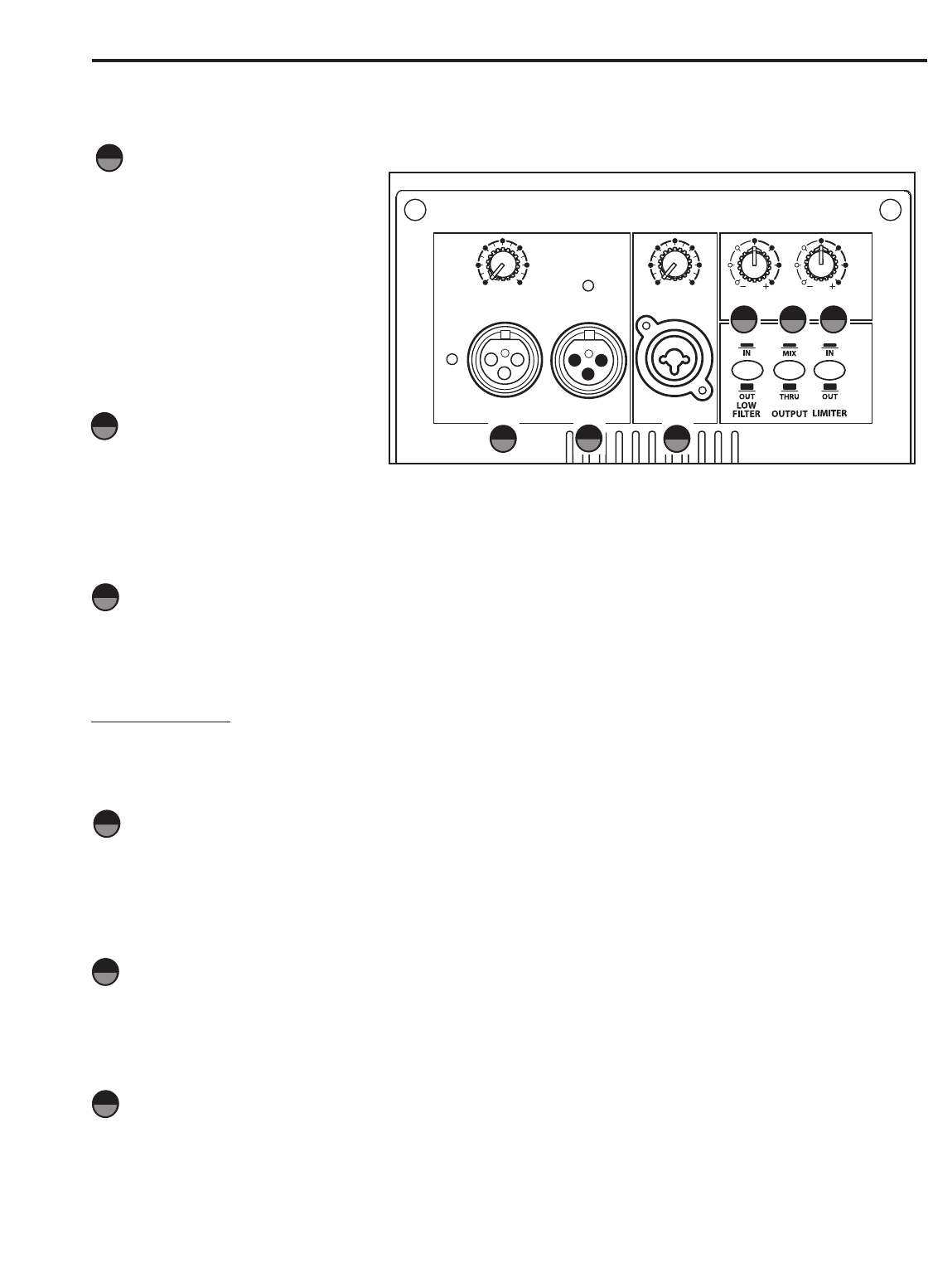
PROTECTION
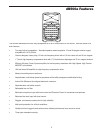
SAMSON
MIC LEVEL
010
AMP / CLIP
LINE OUTPUTMIC INPUT LINE INPUT
LINE LEVEL
0
10
12 1212 12
8888
4444
EQUALIZER
LOW 100Hz HIGH 10KHz
PEAK
8
10
9
7 8
10
9
11
11
12
12